Micro-Tel MSR-904A Microwave Receiver: a set of new handles

For a while I have been looking for a set of of spare handles for the MSR-904A, but to no avail; the unit was missing the handles – had some rough rack-mounting fixtures. Fortunately, most of the Micro-Tel equipment uses the same kind of handle, so at least I know how they should look like.

handle micro-tel

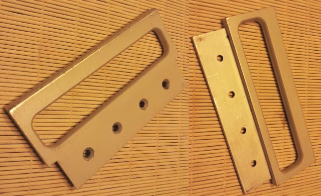
These handles are actually of a very nice design, and don’t look too complicated to fabricate. So I thought I would give it a try and machine a set of spares.

For the material I selected a piece of 7075 alloy T651 temper (fully hardened, stress relieved). This is a quite strong alloy, and it needs to be because the MSR-904A is heavy, and the full weight rests on handles if it is set down on the floor/carried around, etc.

How to machine such handles – well, it is best done using a CNC mill, and luckily, I have one in the basement, even if it is just a small machine.
fkm349vl mill

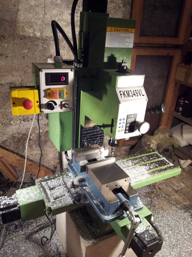
It is a FKM349VL table-top mill, not a very heavy machine, but pretty capable if used correctly. This is not for heavy loads and throughput-optimized toolpaths, but it can yield very usable accuracy, and the surface finish is very nice, provided that good tools are used. Typically, I get parts that are reproducible to within 0.01 mm, and absolute accuracy typically better than 0.03 mm, depending on how the machining goes.

handle intermediate pieces

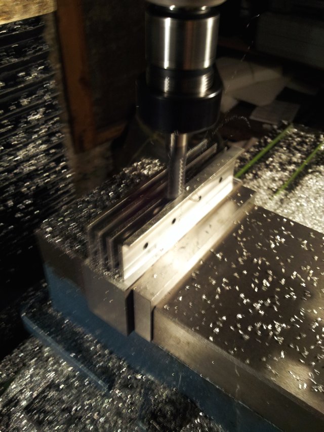
Starting from a plate, first, the opening of the handle was machines, and chamfered. The original handle uses a radius chamfer, but well, I only have tooling for 45° chamfers around, fair enough.

Then, the holes were drilled, and countersunk, followed by machining of the left and right (short) edge.

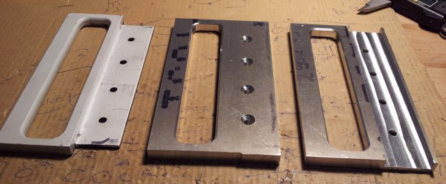
A bit more tricky, the piece where the handle is mounted to the case. This is fairly thin, and some excess metal was left to allow easy clamping of the piece. Sure, there are other ways of achieving the same result, but it saves a lot of time if the vice doesn’t need to be re-adjusted, and if everything can be done in two or three clamp positions.

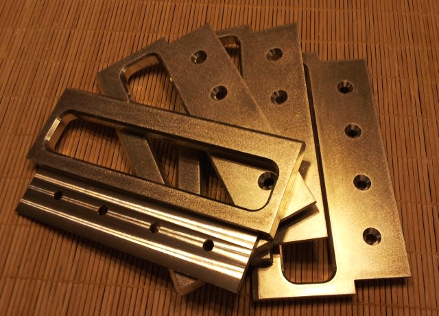
As one of the last steps, the excess metal is taken off.

handle removing excess

All in all, considerably more effort than I thought:

(1) Cut the plate to approximate size; machine one long side flat

(2) Machine handle cut-out

(3) Machine chamfer (upper side)

(4) Machine left and right edge (short sides)

(5) Spot drill, drill, and countersink holes

(6) Turn around – align

(7) Machine other chamfer

(8) Machine mounting piece

(9) Mount set of 4 pcs upside in vice

(10) Cut-off excess

(11) Cut recess of mount piece, left and right

(12) Machine front chamfer, 2x

(13) Deburr, finish

handles final

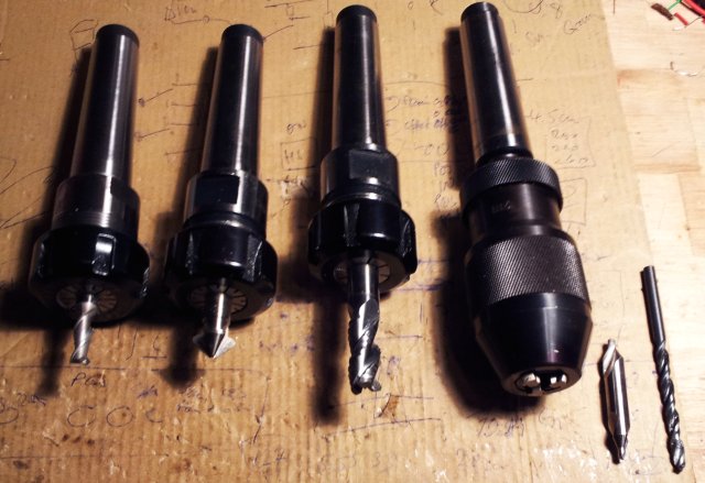
These were the tools used –

handle tools

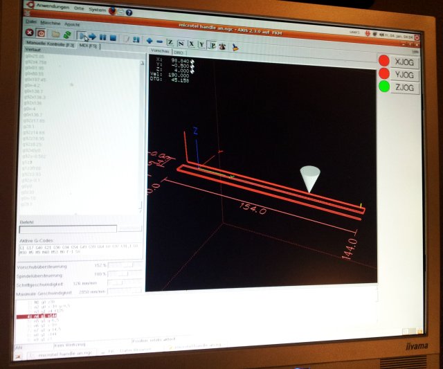
And, not to forget, EMC2 with the Axis interface. Thank You EMC2 (LinuxCNC) team for providing such great software, free of charge!

handle axis

I might still anodize the handles – but first need to do some tests with 7075 alloy (never anodized this alloy before, and don’t want to waste the handles!).

Xmas Bakery: Nougat Plätzchen(=small cookies)

These are one of my favorite Christmas “Plätzchen”(=small cookies). A kind of nougat shortbread, covered with chocolate.
First, prepare a dough by thoroughy mixing/kneading (no machine needed, best use your hands):


250 g nougat (soften in microwave)

80 g butter (soft)

60 g sugar

300 g plain flour, German Type 405

1/2 teespoon baking poweder (throughly mix with flour)

a little bit of salt

1 egg

some vanillin powder (or vanilla essence)

Once properly mixed, make two rolls, and wrap in some plastic foil:
nougat

Let rest for several hours in the fridge, or overnight.

Then, form nice cookies, either manually, or by rolling it to about 3/16″-1/4″ thickness. Don’t roll too thin!

nougat ausstechen

nougat ready for oven

Bake in oven at medium temperature. For best result, use 165°C circulating air. Baking time is 10-12 minutes.

Let the cookies cool to room temperature. Eventually, your efforts will result in a pile of cookies ready to be chocolate-coated.
nougat baked

Then, melt

200 g baking chocolate

150 g of really dark chocolate

using a water bath (also to keep the chocolate warm during the coating process).

nougat chocolate application

For guests that are worried about too much chocolate, it always is a good idea to leave some of the cookies partially covered.

nougat final steps

Use non-stick paper, and let the cholocate solidify for at least 18 hours before packaging.
Store in odor-free, dry place. For best taste, let them rest for at least a few days.

Xmas Bakery: Christstollen

The time is right to get started with some Christmas bakery. Stollen, a long standing German Christmas tradition. It comes in various kinds and modifications, but there is only one truely original recipe.
Don’t use any self-rising flour, or baking powder – really Stollen always uses yeast to rise.

1 kg plain wheat flour, Type 405 according to German industrial norm (DIN) no. 10355

60 g of baking yeast (about 1.5 regular yeast cubes), can be subsituted by active dry yeast, but the real thing is always baked with fresh yeast, commonly available at all German supermarkets.

250 mL milk (warm up; not too hot!)

First, to get the yeast started, put all flour in a suitable bowl (plastic bowl most prefered), make a hole in the center, put in the yeast and mix with some milk to form a semi-liquid dough. Cover with some of the flour, and let it sit for 30 minutes.

stollen yeast

This is how it should look like.

Add:
1 egg, 1 egg yolk (some traditional recipes don’t use eggs, but I highly recommend it, otherwise, it will be a pretty ‘flat’ Stollen, unless you have a suitable mould)

180 g sugar (extra pure saccharose – just kidding; refilled with ordinary, plain sugar)
stollen extra pure saccharose

200 g butter (room temperature!)

and, the remaining part of the milk.

My traditional recipe doesn’t need any almonds – but these are common additions to other Stollens. Therefore, you might add 125 g of ground sweet almonds, and 50 g of ground bitter almonds, along with some more milk.
Also, you can add mace spice, but not too much!

Knead to a firm dough. If too dry, add some more milk. Don’t add too much, dough should not be sticky or too soft! Properly knead with your hands. No machines are required for this recipe.
Let this dough raise for at least 60 minutes at a warm place.

In the meantime, we prepare the additions:
200 g citronat (rather finely cut!) – candied peal of a special type of lemon
100 g orangeat (finely cut!) – candied orange peal
500 g raisins (wash throughly with at least 1 liter of boiling water, and pick out any that don’t look 100% perfect)

stollen ingredients

Key thing is that the citronat and orangeat are finely cut, nothing is worse than big chunks of this in the final Stollen.

Once the dough has rested long enough, the citronat, orangeat and raisins are added – best by flattening out the dough to about 3/4″ thickness, additing the ingredients, and then folding the dough – this will reduce the effort to form a uniform dough.

Finally, form a Stollen:
stollen ready for oven

Make sure to remove any raisins from the surface (these will scorch and give bitter taste) – just push them in, or remove and eat.

Let the Stollen raise for about 30-45 minutes (avoid air drafts, keep in well-heated room).

Then, bake in a pre-heated oven. Temperature: For best result, an electric baking oven is much prefered, circulating air type. Pre-heat to 200°C.
Insert the Stollen. This will help with retaining the shape.
After 10 minutes, set temperature to 165°C, and bake for another 60 minutes (cover with a piece of aluminum foil after 30 minutes).
Test with a wooden stick – if no dough adheres, everything went fine. Otherwise, leave for another 10-15 minutes.

stollen baked

While still hot, apply about 200 g of molten butter with a soft brush.
Cover with a layer of powdered sugar (prefereably, use pure powdered sugar without any other ingredients that are commonly use in ‘icing sugar’).
Carefully wrap in aluminum foil to provide a good seal.

stollen ready for storage

Now, the most difficult part, let it rest for about 4 weeks at a reasonably cool and dry place (guest bedroom, corridor, or similar place that is free of strong odors and free of damp).

Note: this recipe is all in metric units, rather than cups, ounces, etc, because this is about exact replication of a traditional Stollen. This will only work if done accurately, with precise weights, and well-controlled temperatures all throughout the process.

Wiltron 6659A Programmable Sweep Generator: EPROM images captured, some rubber items

The 6659A is running on no more than 10 kilobytes of code, stored in 5 pcs 2716 EPROMs. These were programmed in 1984 – just about 30 years ago. Just in time to capture a copy. Well, not just of their exteriors.

6659a eproms

Their contents –
wiltron6659a
-also contained are the data of the 4 frequency correction EPROMs.

Looking through the board, a very intriguing part: a DAC72C-CSB-I
6659a dac72c-csb-i

It is a 16 bit DAC, 30 ppm INL, 7 ppm/K gain drift. Merely, a resistance ladder, with a build-in 6.3 V reference. Still going for about 40-50 USD each! Very impressive case, for 1984 vintage, and still working just fine, to the current day.

While silicon chips last, rubber is subject to aging – in particular, the 4 rubber stand-offs that were holding the fan. Removal was no easy task – they were glued in with some Loctite, but eventually, I could remove them, and they were replaced by regular screws – not too much vibration anyway.

6659a rubber standoffs

USB RTL SDR 28.8 MHz Reference: VCXO

One of the shortcomings of the USB RTL SDR devices is the build-in oscillator. It is actually very stable and sufficient for all kinds of everyday uses, but I am using these SDR devices for narrowband applications, with down-converted microwave signals. So utmost frequency stability is a must.

Not only needs to frequency be stable, it is also a good idea lock all oscillators to a common reference, which typically is derived from a 10 MHz rubidium source (like in my lab), or a GPS-controlled VCXO.

How to get from 10 MHz to 28.8 MHz – well, not all that difficult, but needs quite a few parts. First, we need a circuit that can receive 10 Mhz signals, and clean them up and prepare them to be used by a PLL. Then, we need a VCXO (voltage controlled quarz oscillator) that can be tuned by the loop filter of the PLL to keep it at 28.8 MHz. The loop BW will be very very narrow, a few Hz at maximum. Comparator frequency can be up to 400 kHz, the largest common divider of 10000 and 28800; but I might select a value more like 100 kHz which can be readily derived from a 10 Mhz reference. There are plenty of programmable PLLs around, but I might just use a hardware solution here (only need to put together :288 and :100 dividers using some TTL logic).

The circuit-
rtl sdr 28-800 MHz ref pll

– nothing too fancy, and still needs some fine tuning. The xtal, it’s the original part de-soldered from the RTL SDR stick. These are actually pretty stable and well-behaved, at least for the devices I sourced from China.

The circuit employs a Pierce oscillator, build around a J310 FET. This is coupled into a common-bias amplifier, another J310, which provides the low output impedance. A matching network is added the make the circuit rather insensitive to changes in the load impedance. The circuits draws about 20 mA at 12 V. Not quite a power safer, hey, but this is not the objective here.

The items circled are just temporary parts, will need further optimization.

The big question – tuning range (pullability) of the xtal. Ideally, it should be a few 10s of ppm, to give the PLL some room to operate, and to account for aging effects over the years. Temperature-induced changes are on the order of a few ppm (see earlier post); but there is also drift, and other factors.

A quick test with some capacitors, and, stable oscillation can be found in a range of -1.8 to about 1.8 kHz around the 28.8 center frequency, this is quite satisfactory.

rtl sdr ref vcxo circuit

At the moment, still run with fixed capacitors, but I will add a varactor network to provide about 8 to 40 pF tuning capacity, by voltage input.
In an effort to keep phase noise down, I might employ a circuit used a lot for earlier projects, with anti-parallel varactor diodes.

rtl sdr ref 10 pf

rtl sdr ref 37 pF

The spectra look pretty clean, and the power is as expected, about -10..-6 dBm. I will use this output to drive the PLL, and add another amplifier to drive the RTL SDR R820T reference input – well shielded from everything else to avoid spurs from the divider and PLL circuits.

A quick test of the phase noise – hooked it up to a 3585A Spectrum Analyzer – there are some mains spurs, which will be reduced by adequate filtering once the circuit is fitted to a shielded box. Other than that, nothing really suspicious. All very close or at the noise floor of the 3585A.

10 pF sdr ref0

3585a noise floor

HPAK 3455A Digital Voltmeter, 34401A Digital Multimeter: switch-on behavior

It is often assumed that high precision instruments are better not switched off but left on running 24/7, just because it is to tedious to wait for the specified “warm-up” period. Mostly, this seems to be more of a habit than a real requirement, at least for multimeters and their build-in references. Let put it to a test.

With all good references back in Germany, we first need to fabricate a little substitute, a +5 V reference based on a MAX6350. This has roughly 0 ppm tempco around ambient temperatures, and +-0.02% initial accuracy.

max6350 5 v reference

Some caps were added to keep noise down.

With this reference fully ‘warmed up’, two instruments were used to monitor the output, a 34401A, with current calibration, and the recently repaired 3455A, with about 4 years old calibration.

The result:
3455a vs 34401a switch on

The 3455A provides 10 µV resolution, in the 10 V range. The 34401A – the displays shows 6.5 digits, same as for the 3455A, but the build in resolution, when read through GPIB, is about 1.3 µV.

As you can see, there is really no warm up. It is stable to ppm level, after a few seconds.

The offset of the two meters:

3455a switch on

About 4 ppm difference – not too bad; certainly, well within spec of these two instruments.

HPAK 3455A Digital Voltmeter: some cleaning, and a really low drift reference

The 3455A is a really nice unit if you are looking for a digital voltmeter/multimeter that is really accurate, and if you don’t want to spend too much. These units go for about USD 100 to 150, not bad, considering their performance – 6.5 digits.

This unit just needed some de-dusting, and was missing some screws. Build some time early 1979 (judging from the data codes, rather than the serial number), this unit doesn’t seem to have hand any issues over the last 35 years – while in service at Northrop Grumman.

Last calibration:
3455a cal sticker

Did a quick check vs the best reference I have in the lab, a 34401A.
3455a check

For a bit more through test, the 3455A was monitored for about 1 hour, with a low noise 9 V source at the input, and the differences logged.

3455a cal offset

Apparently, the 3455A is about 6.7 ppm low, vs. the 34401A. Which one is right, I can’t tell – the 34401A stability specification is about 20 ppm, after 90 days, far worse than the difference of the two meters.

The 3455A has a 11177B reference assembly. It has option S01 – no idea what option this is. HP P/N 03455-66520 Rev B.

The active part, a HP 1902-0926 thermostated Zener – very similar to the LM399, but not in the typical isolated (white) case. One thing is for sure, this part is now well aged!

3455a ref assy

3455a 11177b s01 ref assy board

The reference assembly has some remarkable 0.01% tracking resistors, with 1 ppm tempco – it doesn’t get much better even nowadays, and the resistors are in hermetically sealed cans, with glass seal, except one 1.0020 k +-0.01% resistor in the red resin package.

AC measurements were also carried out in the 10 Hz to 500 kHz range – it seems the 3455A even outperforms the 344401A for flatness, especially at the low end of frequencies.

Wiltron 6659A Programmable Sweep Generator: 10 MHz to 26.5 GHz, in a single sweep…

This instrument just needed a few adjustments, still, very interesting to look at.
It is of a very classical design – 4 YIG oscillators (2-8, 8-12, 12-18, 18-26.5 GHz), a coupler, a detector, and all the driver and ALC circuitry to make this work.
There is also a Wiltron-brand downconverter that provides the 10 MHz to 2 GHz output, by conversion of a 4610-6600 MHz input, with a 4600 MHz LO.

The YIGs are all of best quality, Avantek parts.

The coupler, for the ALC loop, a Krytar ultra-broadband part, with a biased detector.

wiltron 6659a

6659a alc detector

wiltron 6659a yig assy

wiltron 6659a front

The generator provides ample power, 10 dBm or more, over most of the bands; about +6 dBm, at above 18 GHz – and, around 23 GHz, there is a dip in the power curve (see scope screen, showing the ALC/power signal vs. horizontal sweep). Checked the bias (was set at a constant +11 V) – changing it, and going up to +15 V, no change. Also checked the power directly at the YIG output – still, the dip. So it seems, nothing we can do about it, but for most practical purposes, about 0 dBm will be plenty, at any frequency.

wiltron 6659a power measurement

After some more alingments, the frequencies and bands are spot-on (no need to re-programm the linearizer EPROMs – all YIGs are still tracking perfectly fine), some some cleaning, using 50% isopropyl alcohol – done.

The only thing left to be done – a back-up of the 2716 EPROMs that still hold the firmware, after about 30 years.

Dell PowerEdge SC1425, 2x Seagate 3 TB NAS S3000VN000, Ubuntu 14.04.1 LTS: server upgrade

Over the years, a number of manuals and datasheets have been accumulating, also because of my inclination to keep a copy of more or less every document I have used for repair jobs, etc. – sometimes servers go down, and the files disappear in the vastness of the internet.

For some years, I have been dealing with USB drives and NAS storage devices, to keep local copies, and to keep files accessible, but this has become troublesome with space running out, and multiple copies, on multiple drives. Time for a better solution.

(1) A Dell PowerEdge SC1425: 64-bit dual Xeon 2.8 GHz processors, 2 GB RAM. Available surplus, essentially, for the cost of shipment.

poweredge sc1425

(2) 2 pcs Seagate 3 TB drives S3000VN000, these are NAS-optimized drives – essentially, the same hardware as common desktop drives, but targeted for 24/7 operation, with specifications that correspond to long-lifetime “medium”-performance requirements. Performance – this is a private fileserver, and reading rates of 20-40 MB per second are plenty, you don’t need any 10K/15K drives to achieve this.
The drives are operated in RAID1, full redundant.

seagate st3000vn000

(3) Ubuntu 14.04.1 – server. This is a common solution that can provide both Samba (Windows shared folder) and web (Apache) server functionality, at no cost.
Also, it provides the RAID1 functionality (software raid).

Putting these things together, not a big deal – one should think. It took quite some hours to figure out all the settings to get the RAID1 working, and all the files transfered from the old harddrive (~150 GB, the essentials).

Another item to consider, the noise. The SC1425 will be put in the attic, so there is no issue, but don’t consider having this machine anywhere close to where humans reside – it is noisy. 4 fans, cooling the dual CPU, right in the middle of the case (red frame).

poweredge sc1425 2

Some performance stats:

raid1 performance read

raid1 performance write

Roughly 100 MByte/s read/write on the RAID1 pair – perfectly fine to support a 1 GBit/s network speed. Over Samba, I get about 25 MByte/s.
Maybe you noticed the name of the machine – arctur – wondering what it is? – a star, quite a bit bigger than our sun, and not too far away – just about 11 parsec, or 37 light-years! Glad that data server is just a few nano-seconds away, at least, counting the light path.

8645A Agile Signal Generator: power-up, lots of mechanical repair – finally, calibration, and some first tests

The 8645A has been a real challenge. Not electronically, but with all the mechanical damage.

Most of the defective parts are now fixed or replaced, the last one missing:
8645a damaged connector assembly

The front connector and bracket, badly damaged – this will need to go back with me to Germany, don’t have the right tools here (anyone out there with a metal workshop, in the greated NYC area, let me know!). Will see if I can bend this back, or machine a replacement from aluminum alloy. Also, one of the screws is broken off and stuck in the thread – all pretty laborious to repair.

The temporary set-up – connected a SMA f/f adapter, to get the signal out.
8645a temporary connection

Electronically, major success! Not going into any details for now, explaining the inner workings of the 8645A would take hours. But, it is now back to a stage where power can be supplied to the circuits, and watch out, this is the first result:

8645a self cal

… after several minutes, still no change – checked the manual – and the self calibration can acutally take 5 minutes or more, so I am patiently waiting. Finally, this result:

8645a result code 0

Sounds good.

Went quickly through all of the basic functions, and the machine seems to put out almost +20 dBm over the full band, stays perfectly phase locked, and, as far as I can tell with the 8565A, it is pretty clean.

Machine under test –
8645a working

– showing a ~1.7 GHz signal, FM modulated, 30 kHz depth, 1.5 kHz audio.
8645a fm check

For now, repair-final check on hold, with more tests once the connector is back in place.

The many hours spent so far, certainly worthwhile,for a machine that cost about USD 39.5k in 1990, close to 90k nowadays… all its major capabilities, well described in the HP 1990 catalog.
8645a hp catalog 1990