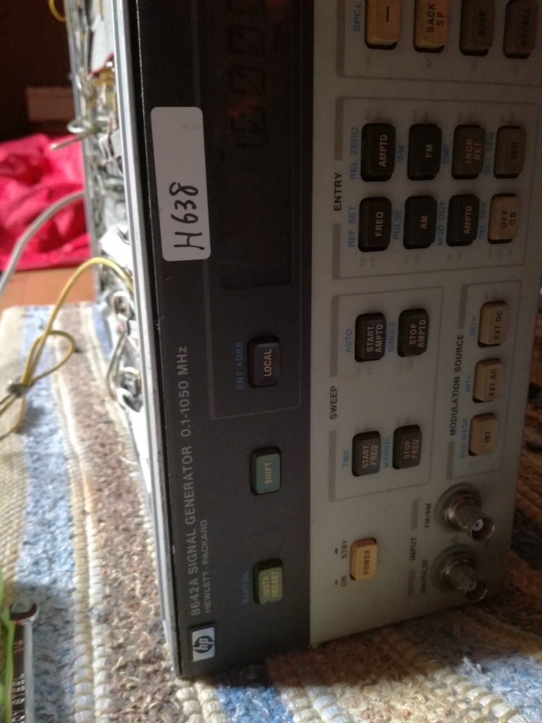
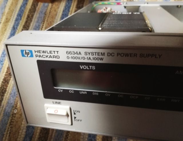
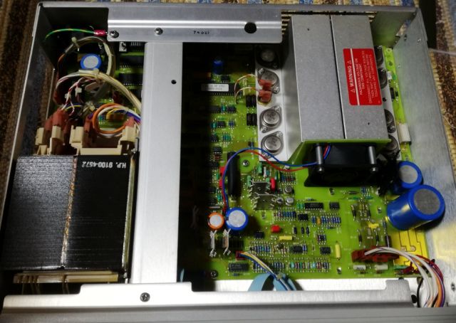
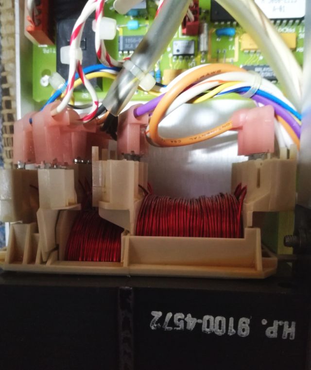
The HP 8642A is the cheaper brother (or sister) of the 8642B (see here, I have two of the 8642B around and still use them quite a lot, one in Japan, one in Germany), it is essentially the same unit, but the “B” has a built-in doubler to effectively double the frequency range. The 8642A works up to 1057 MHz, good enough for most HAM purposes. It has all the desirable HP high frequency goodies inside, including, a set of precision 140 dB attenuators, and a huge number of parts that would come in handy for repair of other RF gear, everything of highest quality, low noise transistor, high reliability tantalums, a box of cables and connectors, and at least 20 kg of case aluminum. So, I did not hesitate to buy this unit for the scrap price of the aluminum contained. It also has a low distortion modulation source, which is also very useful, and has a may high quality relais and opamps.
The unit is somewhat dirty, seems it had been sitting in some storage room for a while, and looking at the fan inside, it also has seen some hours of operation (which is not necessarily a bad thing).
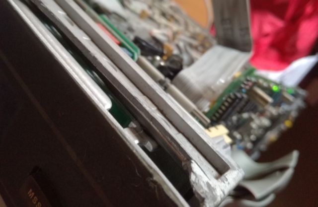
The front frame has a mechanical damage, some part is missing – fortunately, no damage to the front panel. But I have some spare HP System II frames, let’s see.
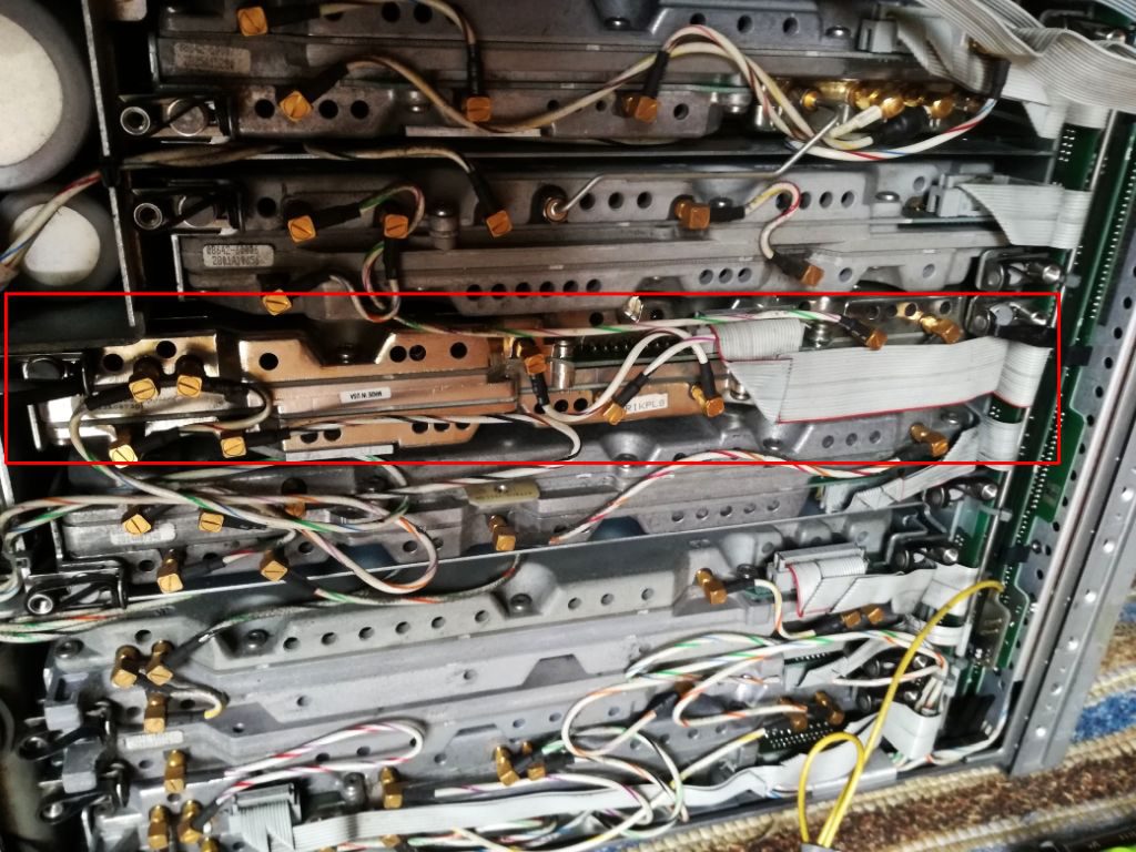
Strangely enough, one module is quite shiny, the case aluminum had some other surface treatment – also, it has a later date code (1989), compared to the other units (1985-87). Upon close inspection of the connectors there are slight scratches – seems this module has been replaced. The 8642A had a field repair program based on module exchange (even the specs were guaranteed after such exchange), quite likely that this module had failed after a couple years of service.
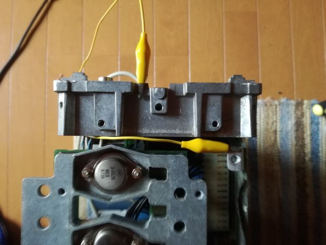
After a quick power up test – nothing to report, the unit is not powering up at all. Took all the panels off, and checked the voltages – nothing present. Checking around the rectifiers and capacitors – all is good here, but the voltage regulators (+-5.2 V, +-15 V, and +-50 V) won’t start up, even when I try to force them. Checked the rails – disconnected the cable (ribbon cable) from the supply assy (A17) to the power distribution board. The 15 V line has a hard 0 Ohms short!
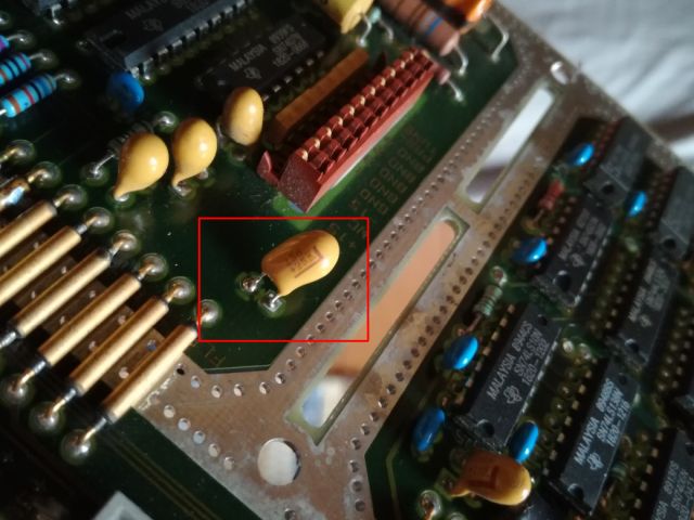
15 Minutes later – checked each module. And the shiny one has the short! A bad 10 uF Tantalum (25 V rated, running at 15 V – should usually be good enough). Replaced it with a 15 uF, 25 V Kemet – no 10 uF Tantalums here in my Japan workshop.
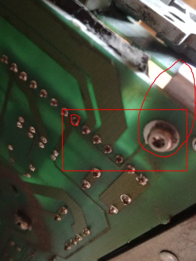
Still, before we proceed, let’s be careful with the power supply. Not that it starts up, and has some issues, and all the modules are gone. Easier said than done – there are sense wires going to the power distribution board, and, a ground sense wire going to the rectifier board (A18). I didn’t bother to study the schematic and notes too precisely, there it says: sense ground, connected to a screw and to the chassis. Of course, I had removed this screw, and now wonding why the supply won’t work…
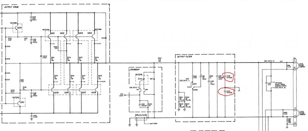
That’s how this screw and trace looks on the schematic.
Fixed it with a jumper wire, still no success.
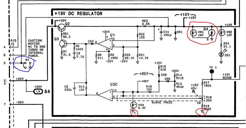
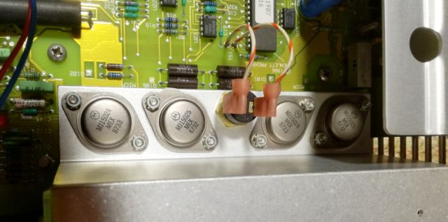
Fortunately, only minor trouble, a dead Zener in the 15 V crowbar (using a Zener-Thyristor-SCR circuit, marked red below). And, by design of the supply, if the 15 V is dead, all supplies stop.
After this fix, the supply is starting up, and all voltages are accurate to 5 mV, with no adjustments… this is real quality. And with the supply, the unit is starting up, and passing the start up self test, and even the extended self test (preset-shift-330-Hz), no issues.
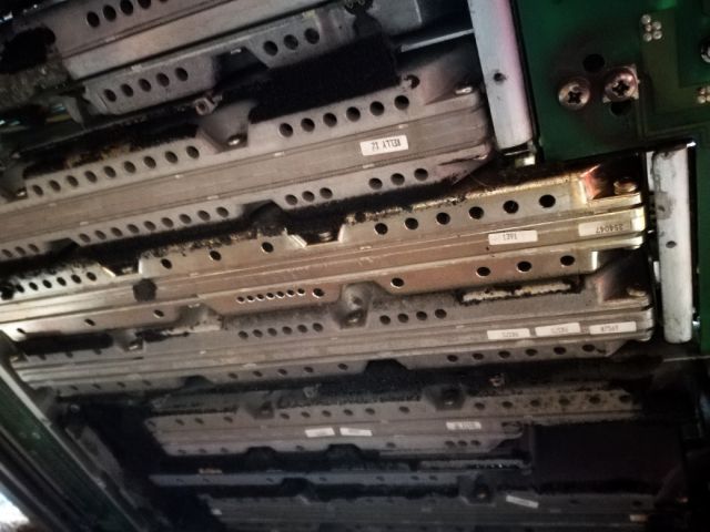
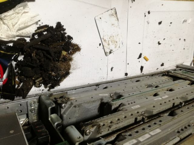
Not so high quality are the elastomeric materials used – two kind of foam, one of low density, which completly desintegrated to a black glue like substance (same applies to the 8642Bs I have, so it is a material age issue, not related to the storage or use condition). First, scratching off all the old stuff with a credit card. The bottom cover was a mess, so I don’t show pictures (couldn’t touch the camera with the gloves).
Everything cleaned off. Below, these are the craps (including a chocolate bar cover, which you will need after this messy work).
The new foam pieces (not shown), were all cut to the precise shapes, and mounted with double-side tape (carpet tape).
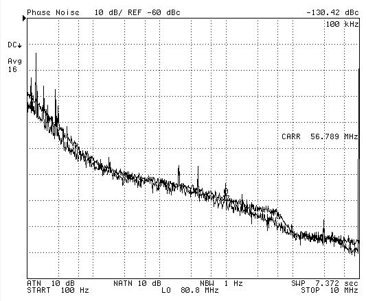
There will be some further repairs needed (the backlight is not working, and I need to get a good front frame from my German junk pile), but some initial tests were done. Phase noise is good, at least as much as I can check, vs. a 8662A, tested at some random frequencies (10 and 56-odd below).
Note, at above 10 kHz, the 8662A has higher phase noise than the 8642A, so the test can only show the overall function and absence of phase noise issues (for the 8642A) above these frequencies.
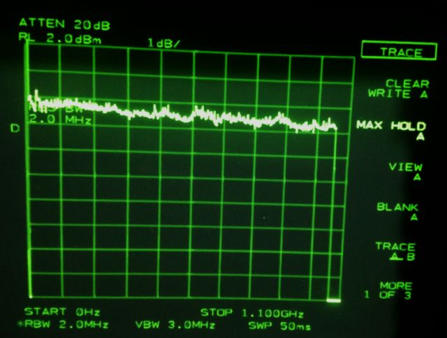
There are issues with the attenuators. And flatness, see below. Even with a rather crude spectrum analyzer as flatness indicator, all within 1 dB easily, over the full span.
All in all, still a good unit, and I won’t yet use it for parts and spares.

