Micro-Tel SG-811 Signal Generator: a second unit

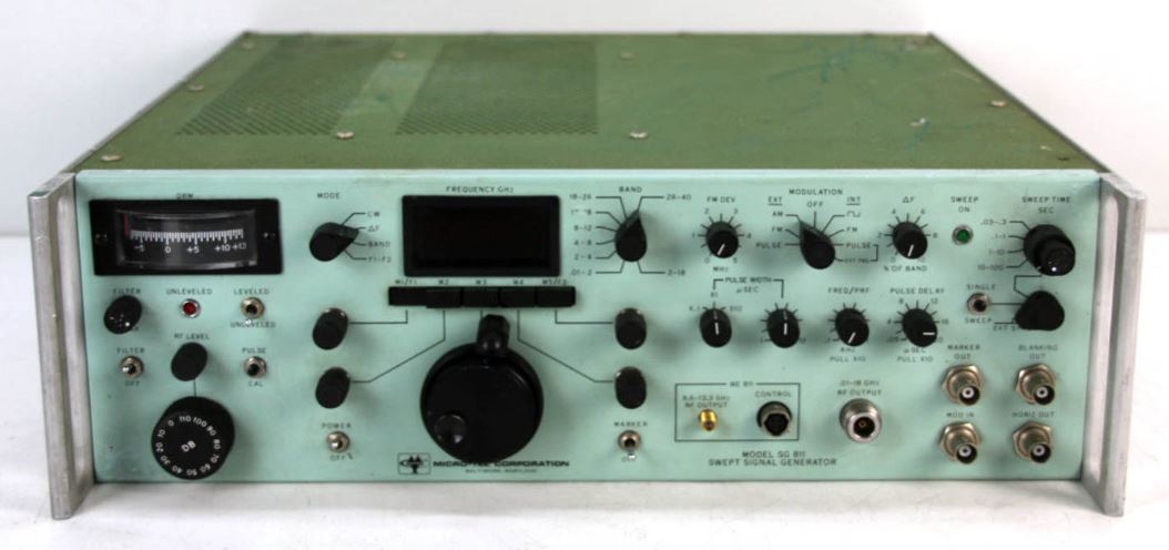
By luck and coincidence, I found another Micro-tel SG-811 generator on eBay, at a very reasonable price – sold as not working. Even non-working, these units are great because of the many microwave components contained: YIGs, filters, GHz-capable relais, SMA cables… and a lot of old-fashioned analog circuits.

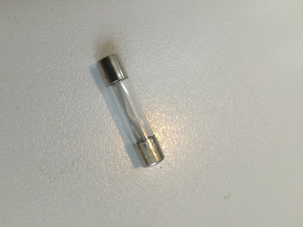
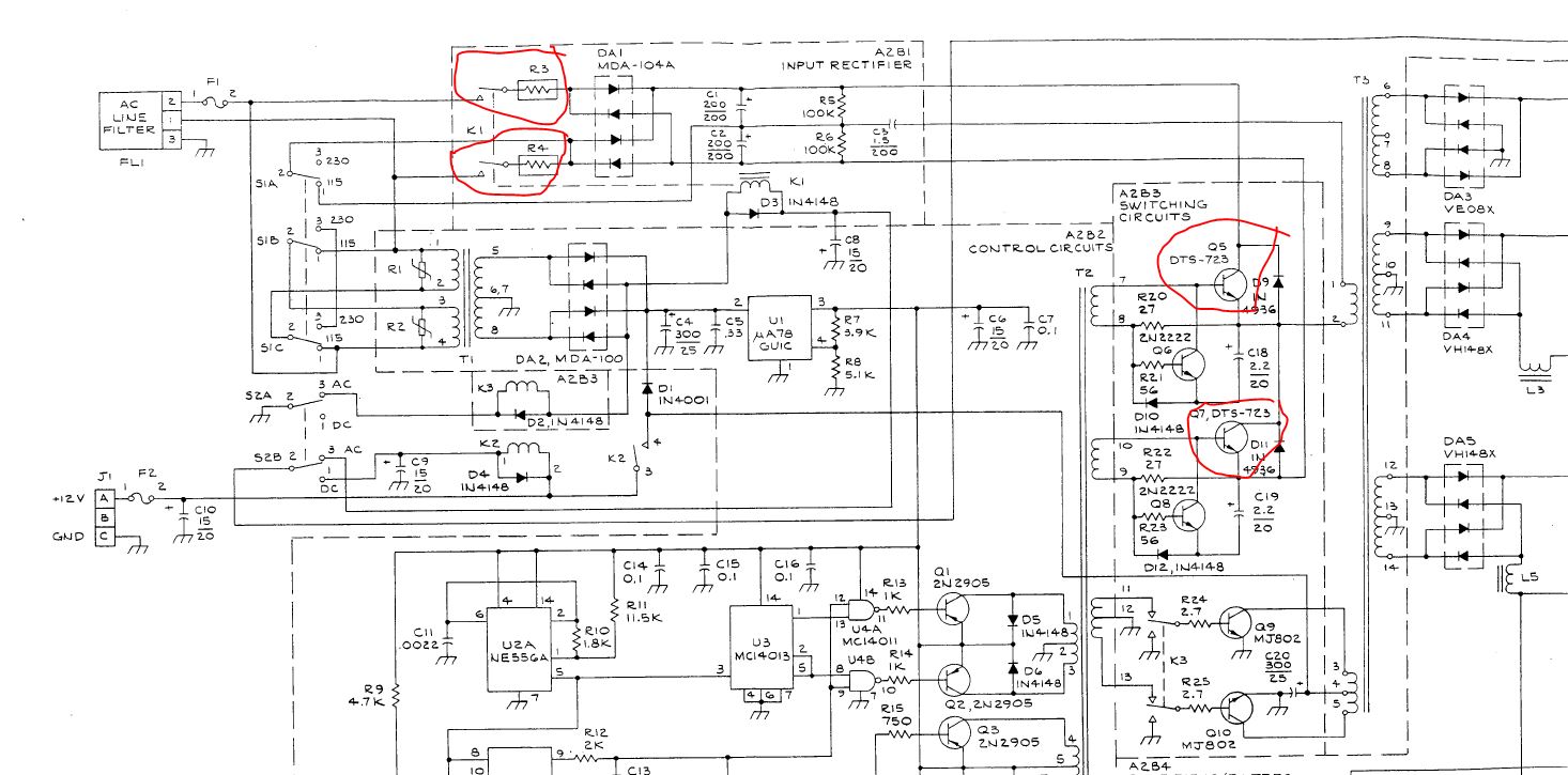
First check – the fuse! Someone recklessly put a 10 Amp fuse in, because the smaller fuses would blow. That’s never a good idea. Most probably we will have to deal with a power supply repair.

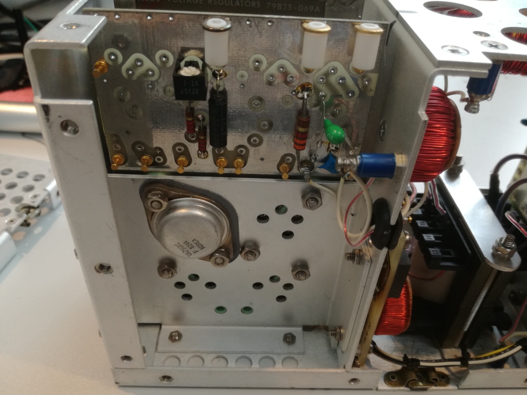
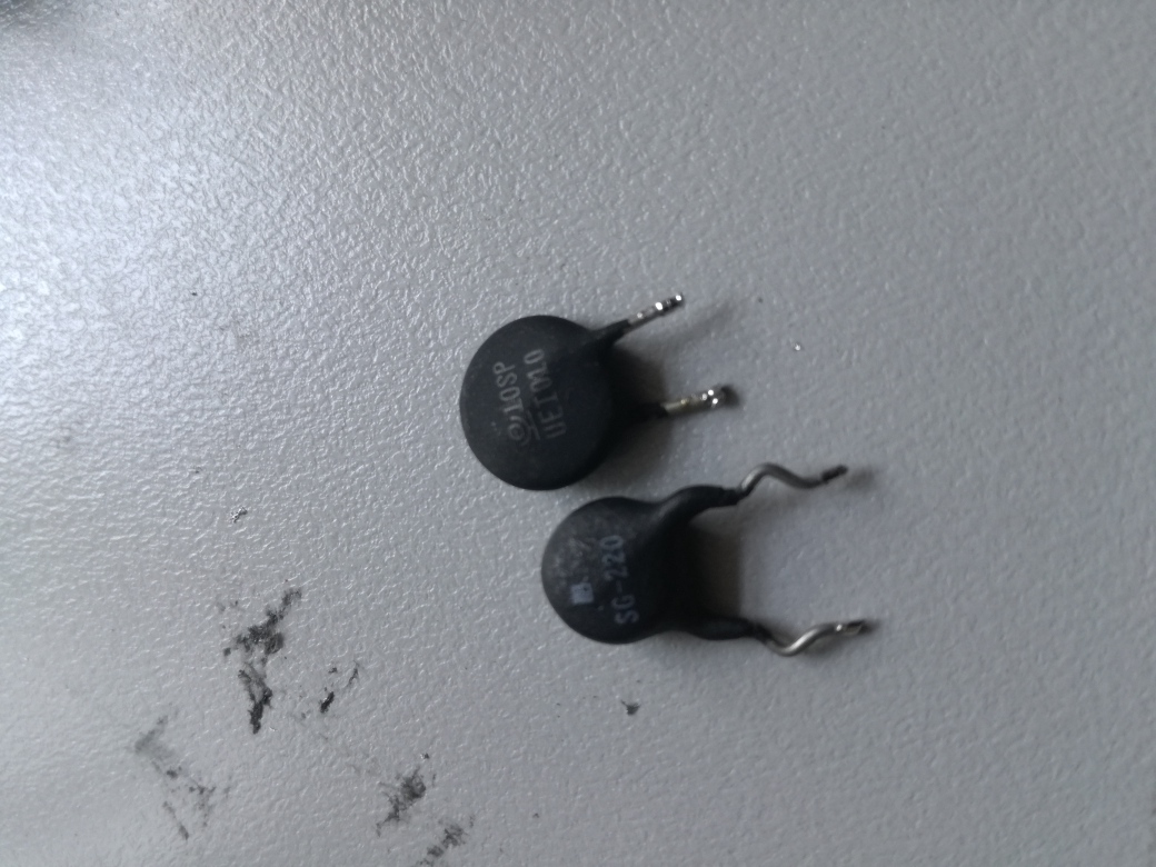
After detail assessment – the 24 V tantalum cap is shorted, maybe this triggered a sequence of faults: the main primary transistors (MJ12002), the rectifier, and two thermistors that limit the inrush current.

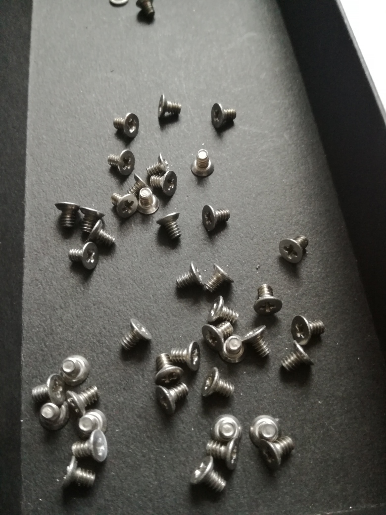
Micro-tel didnt safe on screws when they designed the power supply!!

These power thermistors are hard to get – I just desoldered two similar ones from old switchmode power supplies.

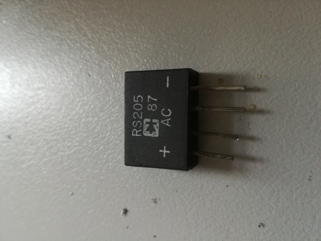
A dead rectifier – easily fixed.

All the parts labeled – also replaced the 2N2222 driver transistors, and two tantalum caps that were leaking current.

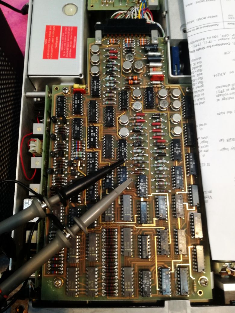
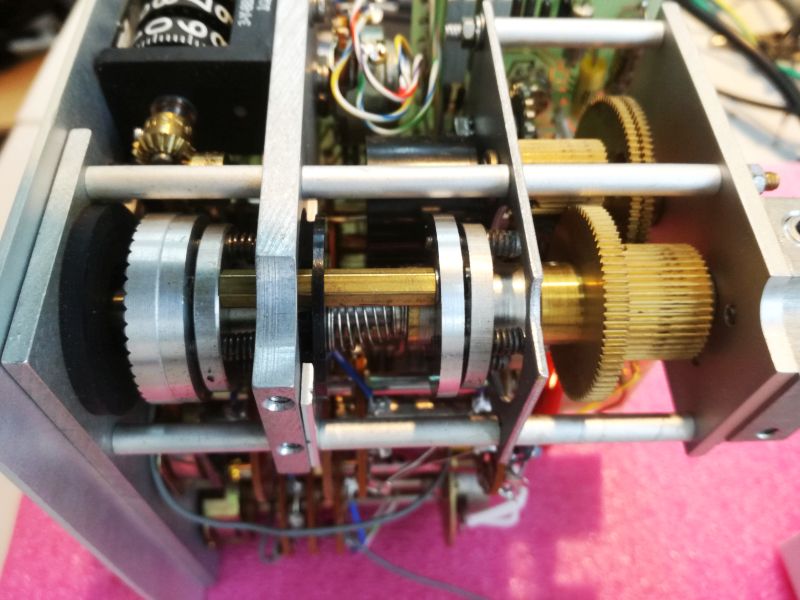
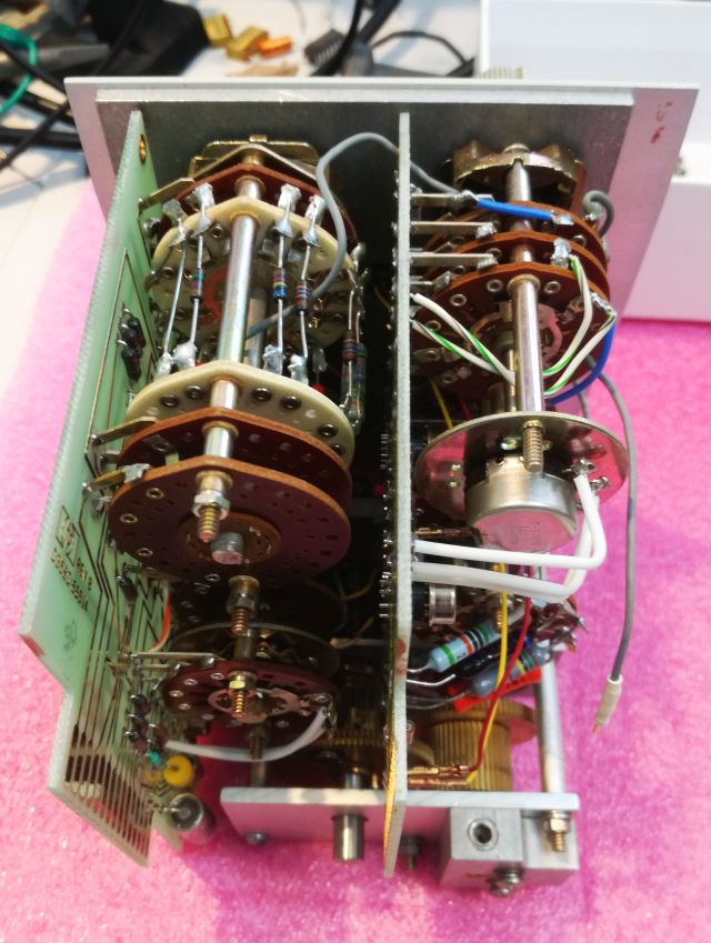
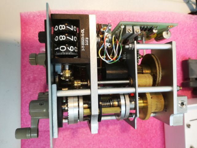
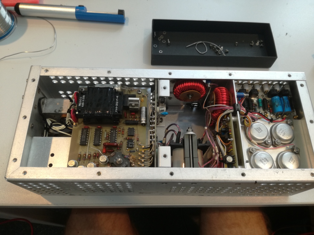
The most precious parts – the RF section.

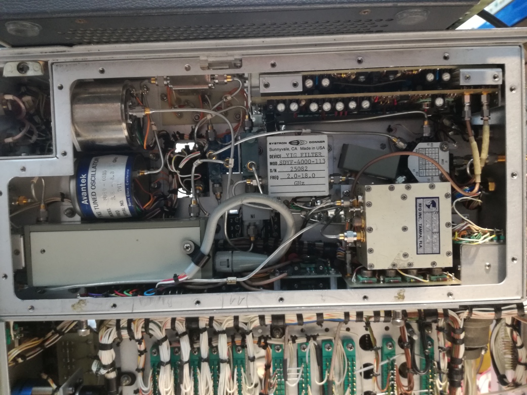
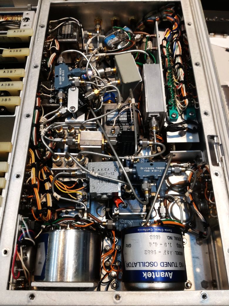
A most complicated arrangement of oscillators, switches, couplers, and so on

Some of the oscillators originally used in these units required a variable supply voltage to get stable power output, but strangely enough, the YIG oscillators fitted have built-in voltage regulators, and the supply voltage has no effect at all on their output. Still, the power supply board caused issues – end even overheated, because the voltage is set by very sensitive trimmers, and drifted above 18 Volt…

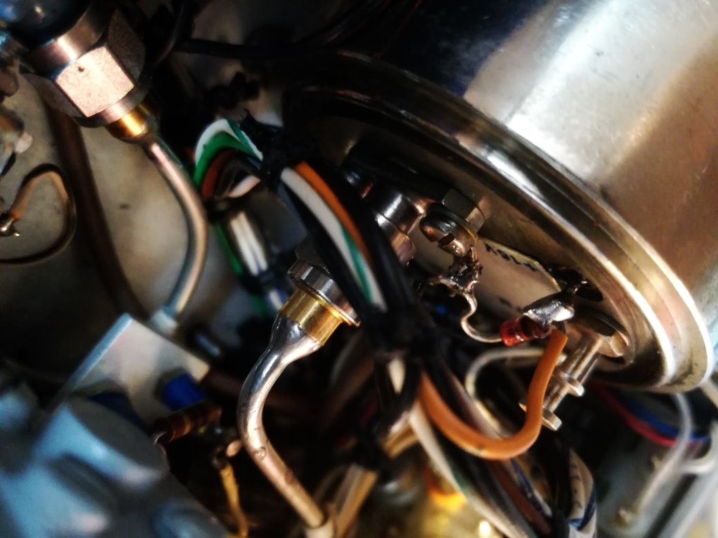
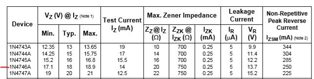
The YTO has a voltage protection diode – it was completely fried when I received the unit. Checked some good Advantek YTOs, these have 18 V 1.3 W Zeners for voltage protection.

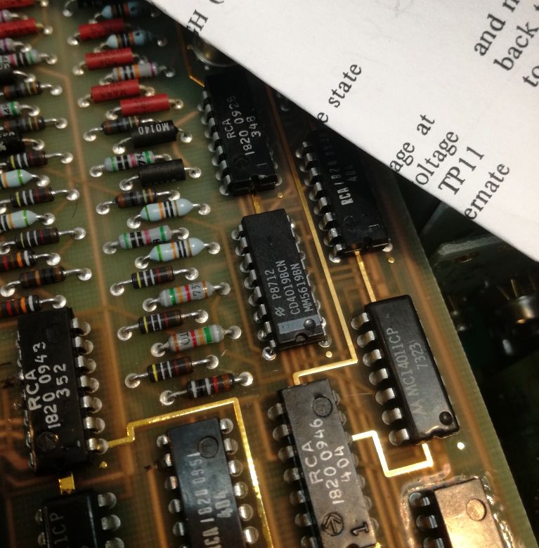
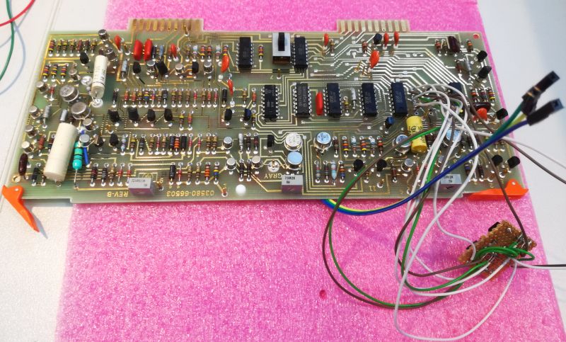
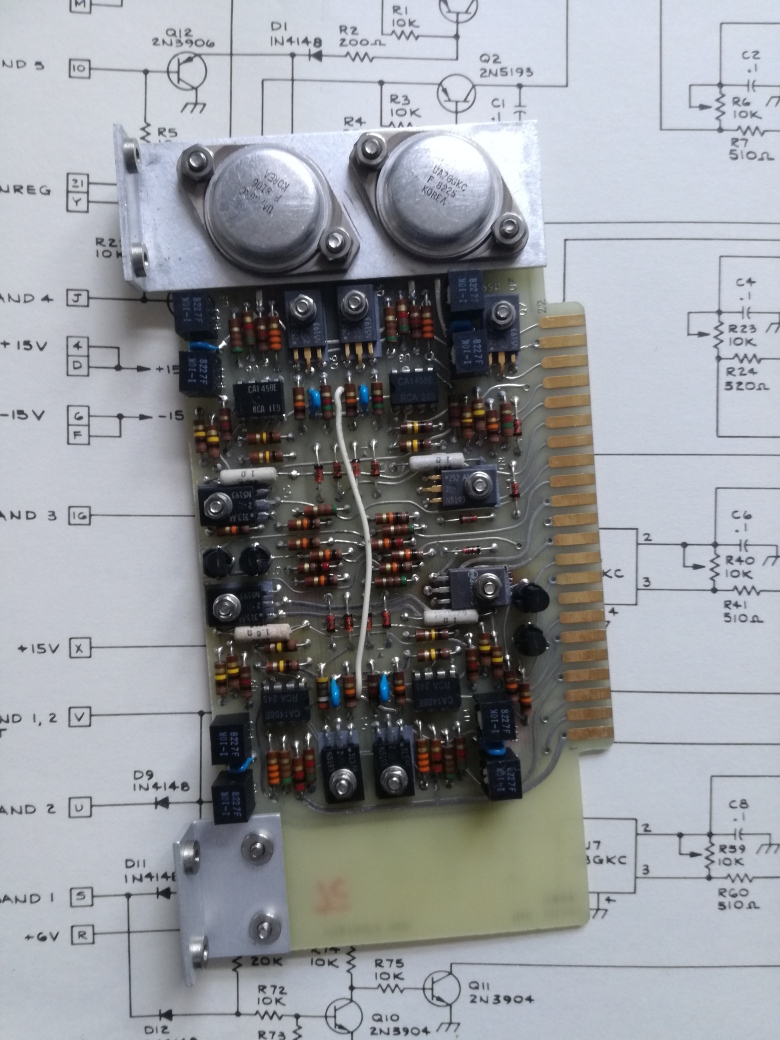
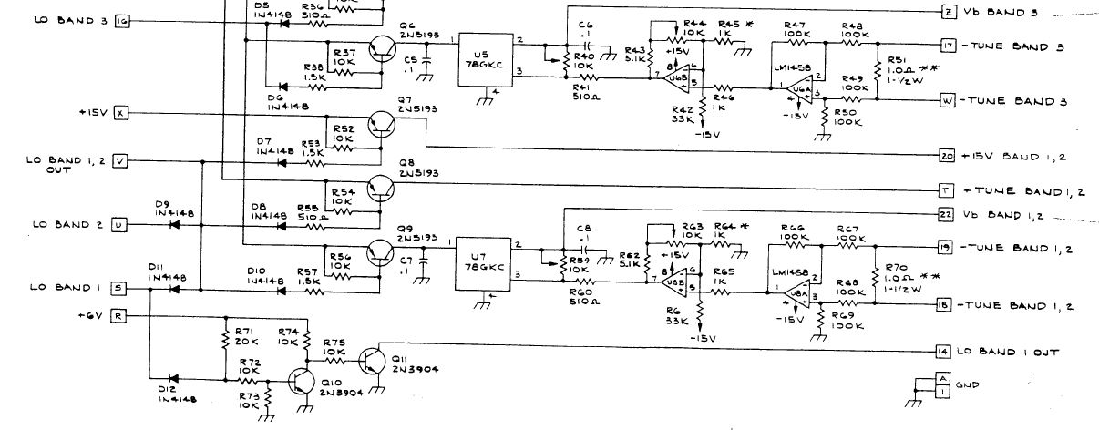
With power back on, and the voltage at the YTOs OK, still no good output – how can it be? Some issues with the oscillator driver board that sets the current of the main coil, and without a proper magnetic field, there won’t be any oscillation.

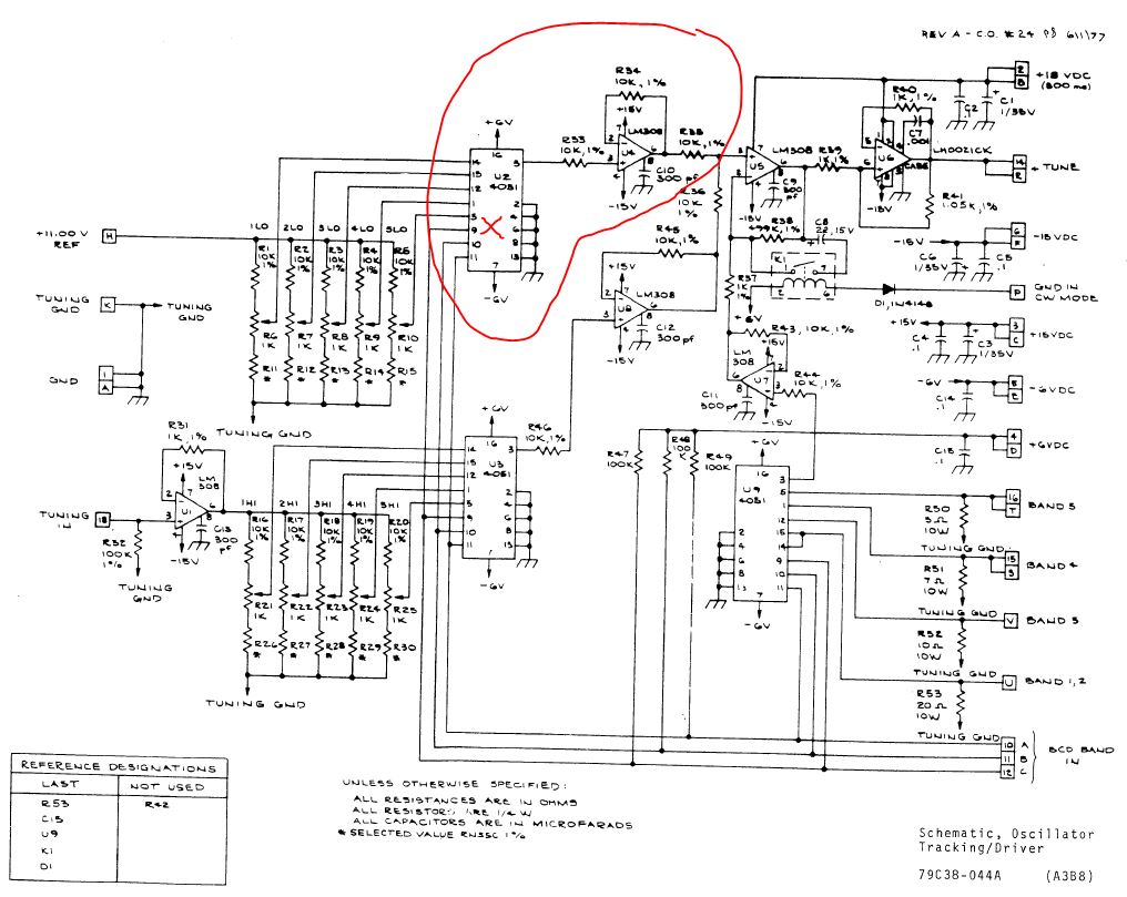
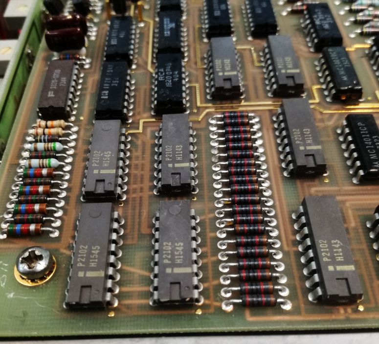
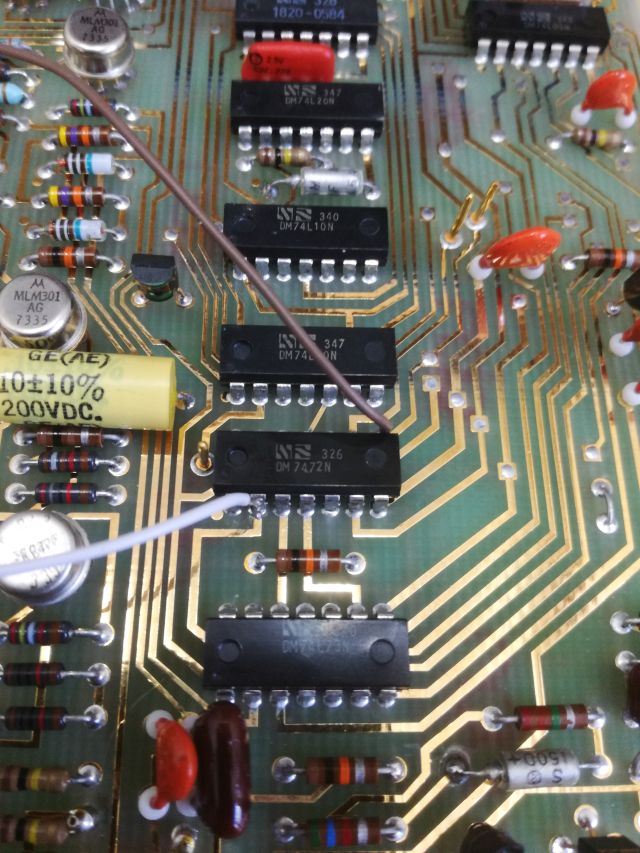
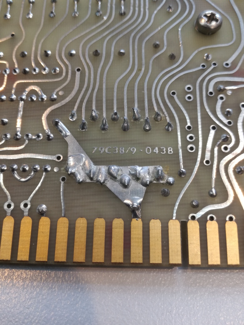
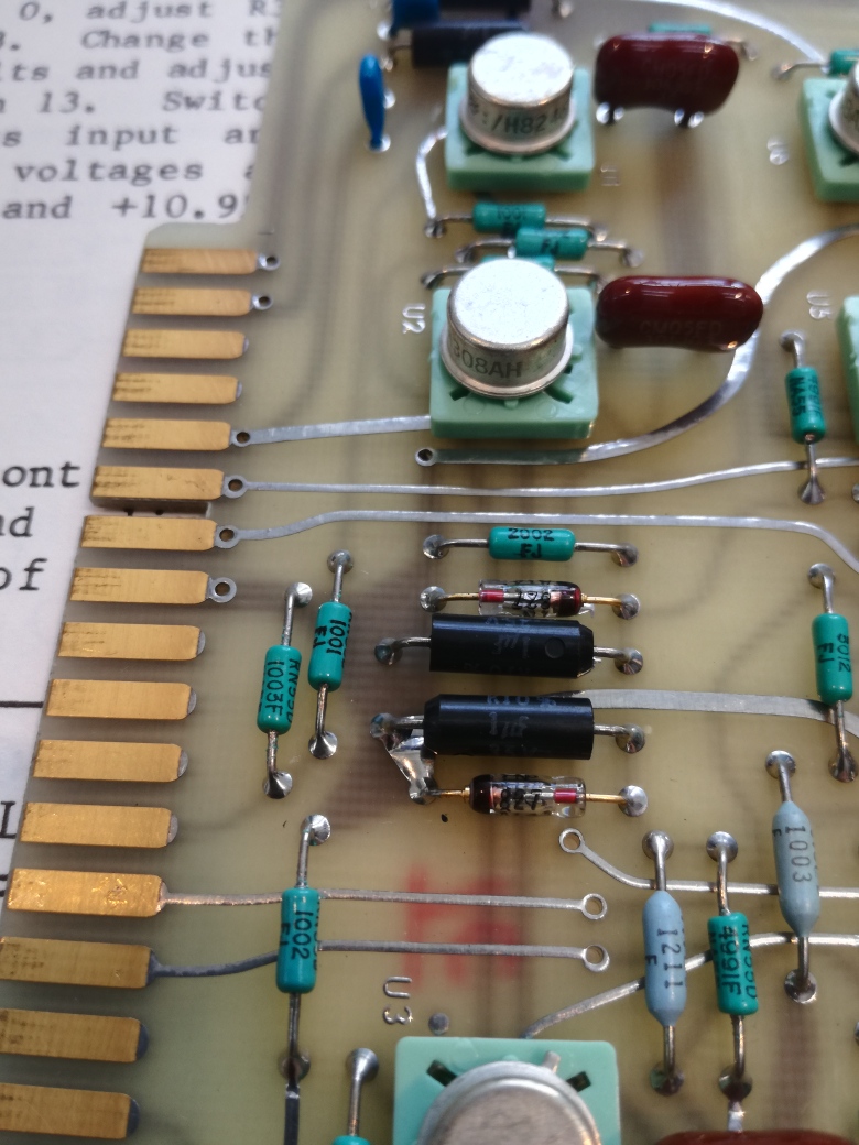
The precision resistors, seems they were hand soldered with some bad solder (traces of corrosion, and high melting point).

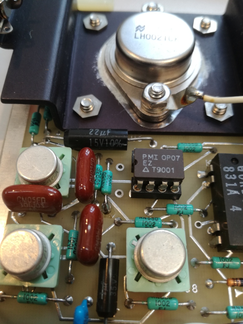
First, some trouble to find the dead part – thought it is one of the opamps, LM308, replaced it with a OP02. But no luck.

So I changed it back to the old LM308, just to keep all in original state.

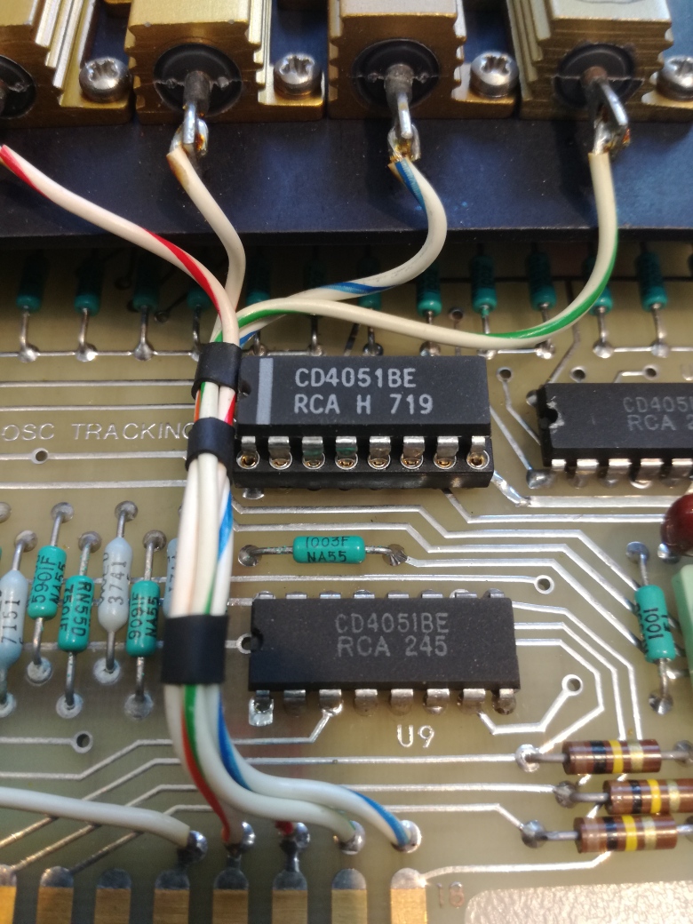
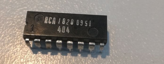
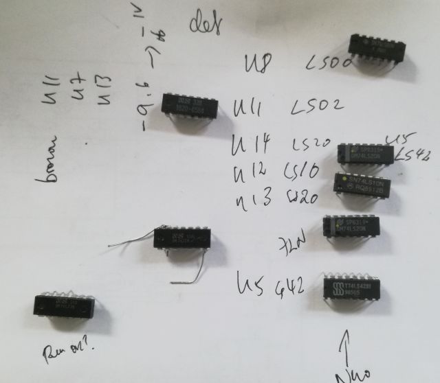
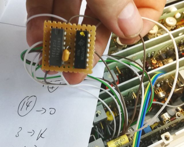
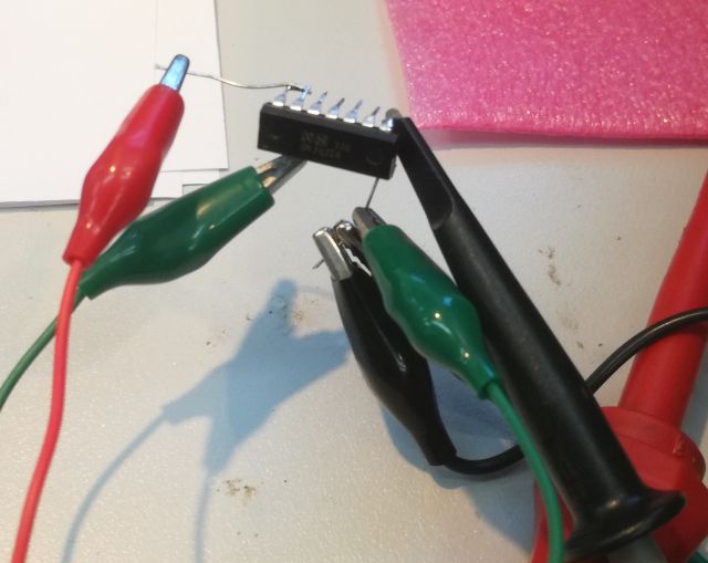
The bad guy… a 4051 multiplexer CMOS, these are notorious!

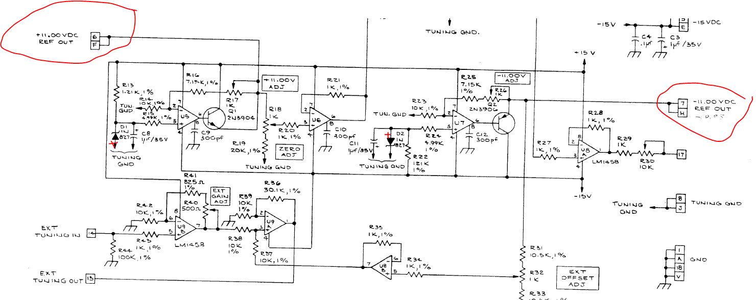
Another interesting assembly, the reference assy – the 1N 827 reference diodes where still very accurately set, only a few ppm of the 11.000 V, and -11.000 V!

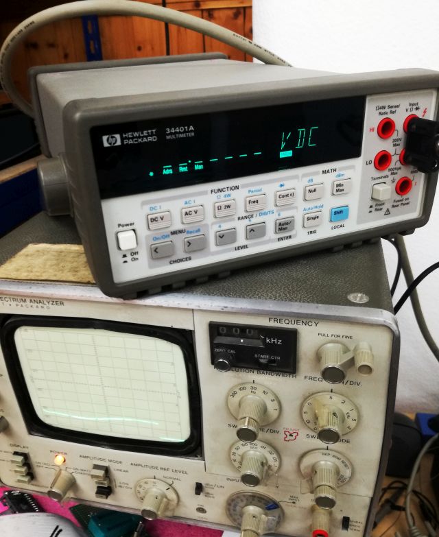
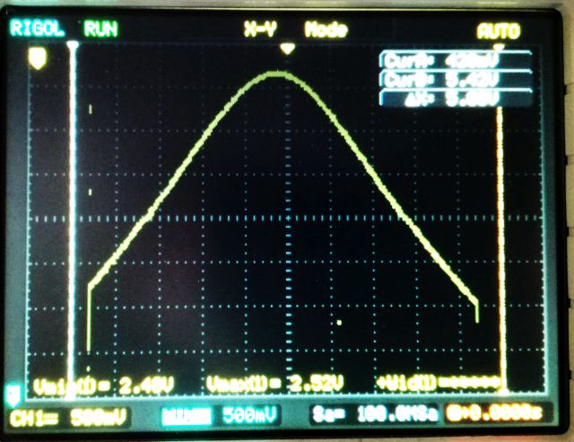
After these repairs, and some adjustment, all is back to working condition!

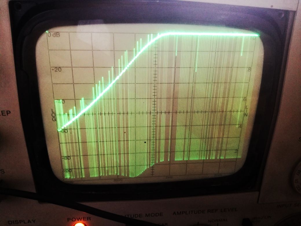
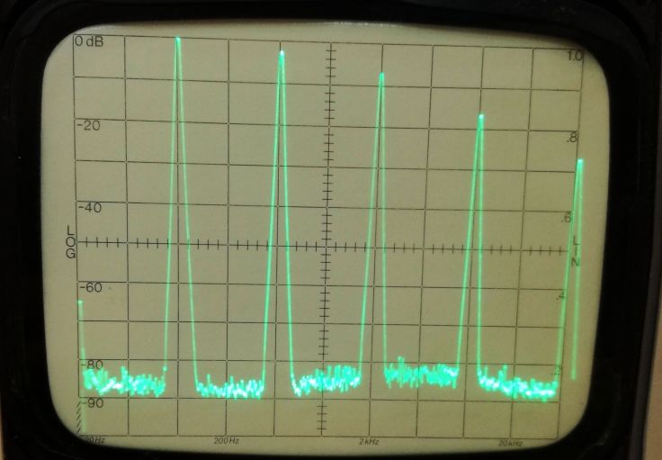
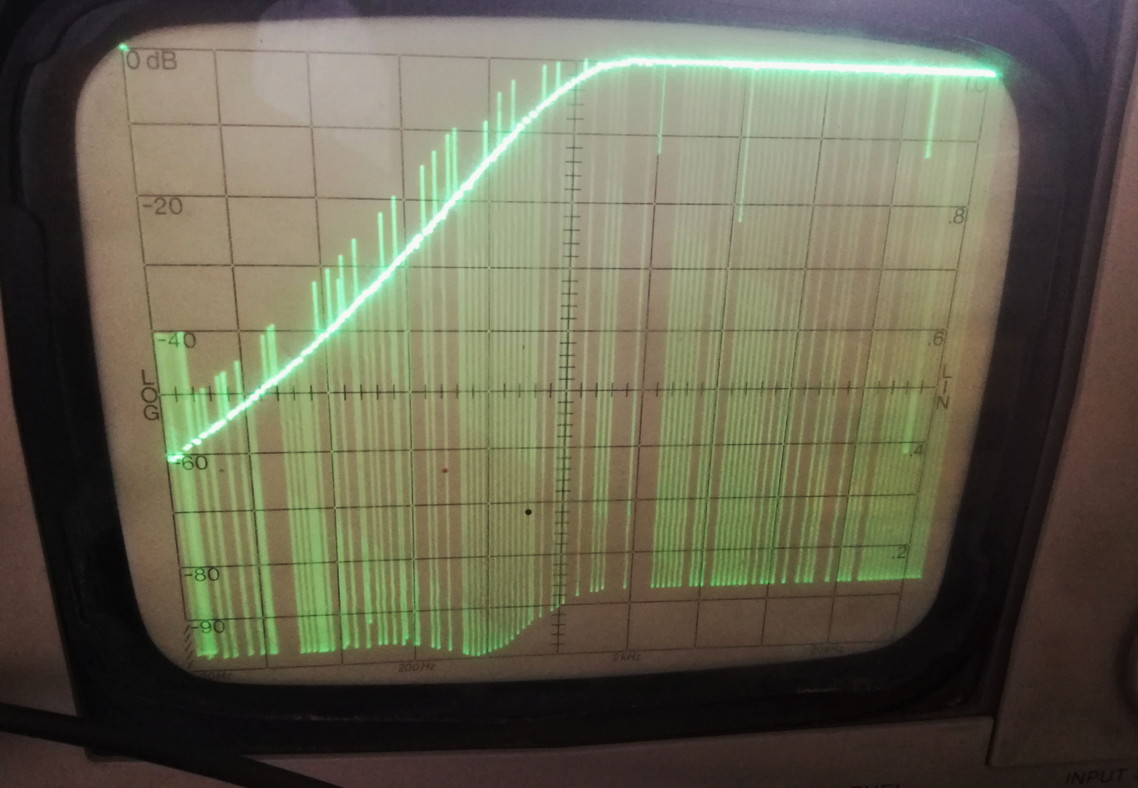
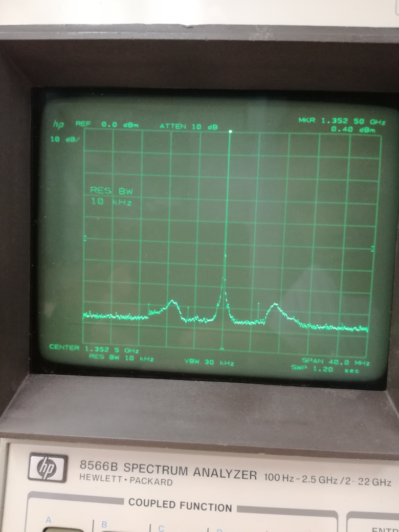
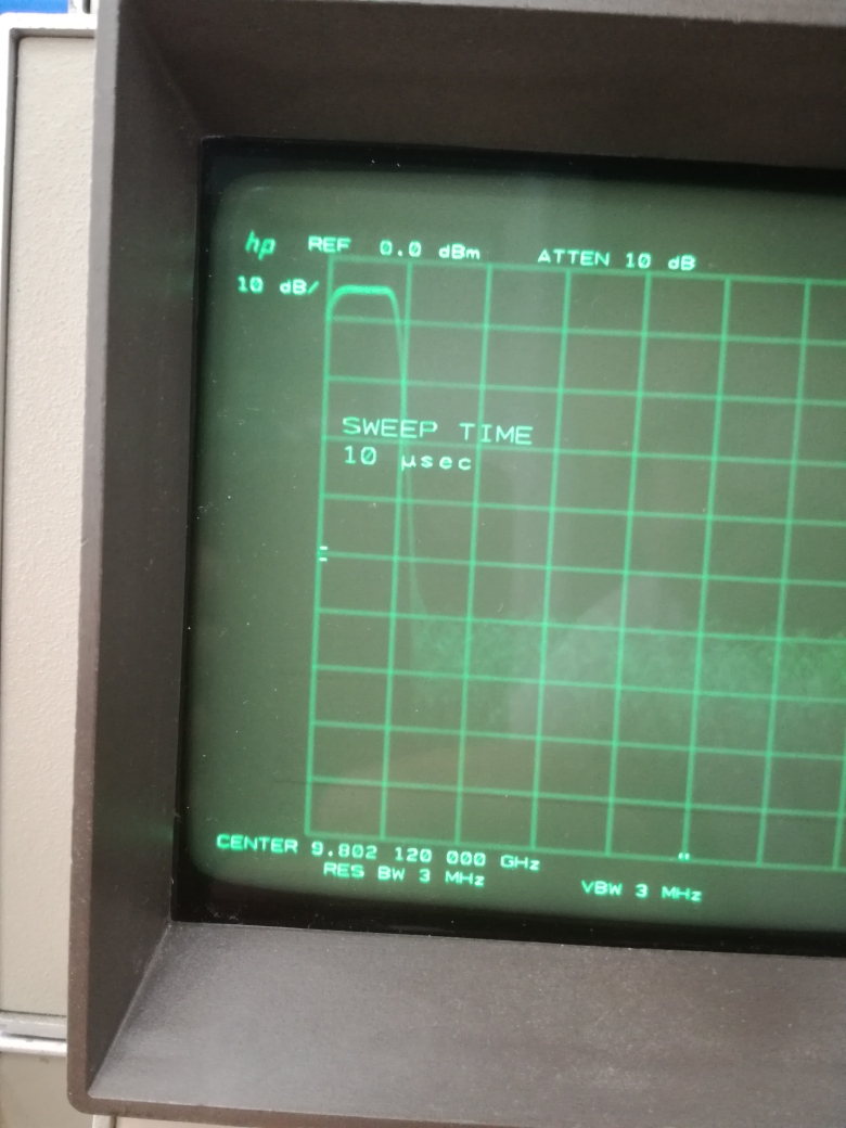
Checking out the signal on a 8566B analyzer. All good!

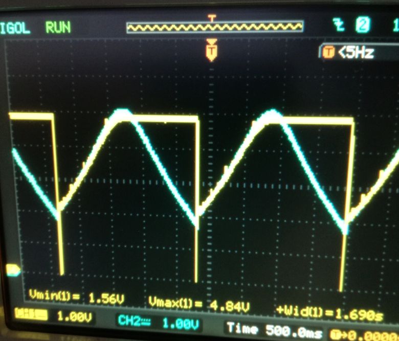
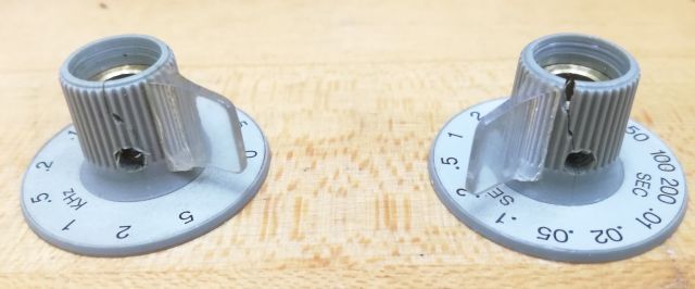
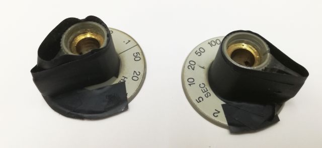
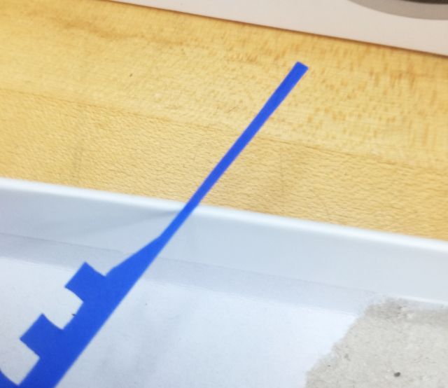
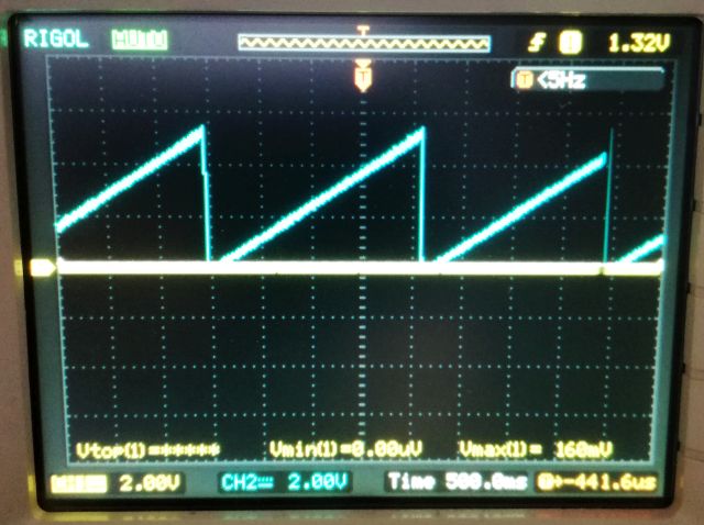
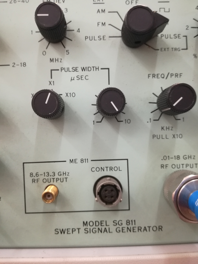
The pulse generator, also a great feature of this unit… 1 ms pulse.

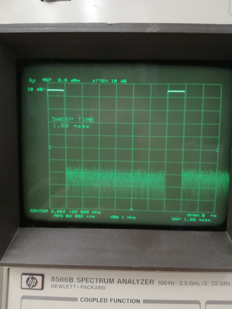
down to 1 microsecond, no problem.

… 10 microsecond pulse…

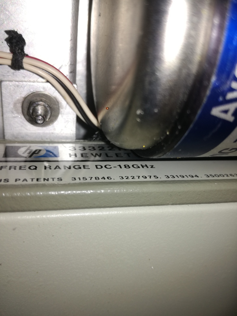
The attenuator, a really high quality HP device.

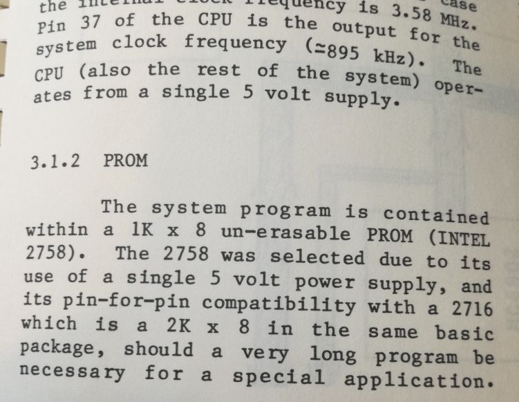
The manual has some remarkable comments – use a 2 kbyte memory, just in case a “really big program” would be needed in the future.

Still, I will do some alignment of the oscillators and filters… but that’s no big deal.

HP 3580A Spectrum Analyzer: Digital display fix, and ancient CMOS circuits

With most of the 3580A functions working again, we still need to fix the digital display. Essentially, the 3580A uses a digital scope circuit, similar to those use in digital oscilloscopes of the 70s.

First, some study of the ADC. The 1973 HP Journal has all the details, it is successive approximation, peak detecting ADC.

Checking the input to the digital display board, blue trace, and the comparator/approximator input to the ADC, yellow. Seems something is wrong with the ADC ciruit, or it’s timing-counter control systems.

After considerable checking and probing, I found the issue, a dead 4019 CMOS, 4×2 multiplexer. Replaced it with a “new” part, taking great care to avoid any static discharge to the board.

The dead part, it is almost a historic piece! 1974, only a few year after the introduction of CMOS circuits by RCA!

That’s the full board. Multiplayer construction. Plenty of precision resistors that are needed for the ADC circuit.

Another working antique part – the 2102 S-RAM, Intel, 1 kbit per circuit. 8 pieces – a total of 1 kbyte of SRAM!

Working display…

10 kHz reference display… Great!

Even the log scale scan is working.

One tip – put all the screws and parts in a box, and check that it is empty afterwards. So many instrumented I receive here in the workshop are missing some screws or other parts.

HP 3580A Spectrum Analyzer: a few mechanical repairs, and sweep test

With the basic functions of the 3580A restored (at least, it is sweeping again), some attention needs to be paid to the mechanics. Fortunately, all is good with the intricate tuning assembly and digital display, but the knobs have some cracks, probably, a combination of age and stress.

Everything taped up, and the cracks filled with rapid-set epoxy resin.

To apply the resin to the small cracks, you can use a piece of stiff plastic foil, cut to a tool of appropriate size –

Here, a few close-ups of the tuning mechanism. It has fast tuning, and fine tuning, a clutch, several gears – all good old analog technology.

Finally, some test of the sweep circuit – but how to test a 200 second per division (i.e. 2000 second per screen) deflection for accuracy and linearity? Well, I connected it to a 34401a multimeter, and recorded the values for several hours by GPIB interface.

As you can see, the sweep is very linear, only some minor deviation at low voltages (maybe connected to some offset voltages or similar effects of the operational amplifier), at least, we can’t see any leakage current of the capacitor, which would show up as increasing sweep time with higher voltage/later divisions.

Also interesting, see the accuracy of the sweep speed, with warm-up of the instrument (each measurement is 2000 second). Still, after all these years, well within the 5% specification of the sweep time! Amazing!

HP 3580A Spectrum Analyzer: a non-working marvel of engineering

The 3580A is a audio spectrum analyzer of the 1970s, and not only useful for audio, but anything that can be converted to audio frequencies (e.g., noise analysis of GHz sources, provided, you use the appropriate mixers). This marvel is not a FFT machine, but a discrete audio “received”, using a low-noise local oscillator, and covering a frequency range from 5 Hz to 50 kHz. The resolution filters are quarz filters, with bandwidth down to 1 Hz! Dynamic range is over 80 dB.

The device, it comes from my old university, and has been sitting there on the shelf for a while, not working. And in fact, it shows not many signs of life, it is not sweeping properly, and even in manual mode, it is not working reliably (not showing any reasonable signal, but there is some activity on the tracking output which suggests that the instrument is not all dead, also the “overrange” LED is working).

After some study and test it became clear the the issue is with the ramp generator. Unfortunately, it is not a simple ramp generator, as you can see below.

The main circuit is a capacitor being charged by a current source (mechanical switch with resistors).

The voltage at the main capacitor, a 10 µF polyester hermetic cap (really high end with glass seal and metal case), is charged and its voltage amplified by a FET-opamp (the FET input constructed from a discrete FET pair, and a PTFE stand-off to keep this all really high impedance).

All the sweeting action is controlled by a state controller, more or less, a hardwired program with several TTL chips. It took me quite some study to understand how it is supposed to work. But fact is, it doesn’t. Clearly, the issue is with the A3 assembly. This must have been quit an expensive assembly at the time, with all the FET pairs and opamps. Still today, not an easy thing to fix.

At least, it is a beautifully arranged board, all gold plated and really smells like quality. So it is worth some time and effort to fix it.

Key for such repair, at least in any reasonable time, are a set of good schematics. Fortunately, I have a set around and printed out really large copies – it is worth the effort, because without making some notes, you will struggle to keep all in your brain and still work on the circuit.

With no extender board available, just soldered some wires to the board to monitor the state of the main state counter, and some of its inputs.

Hmmm, after a lot of probing, I was almost tempted to replace a good part of the TTL chips, because it is really hard to find the defect in such a complicated and loop-wired logic circuit, including its analog parts.

But after a bit more consideration and test, I decided to try a step-wise approach, starting from the most likely parts causing issues. One of the 7473 dead, no problem, there are spares around. But the next one – a 7472! This is an AND gated J-K flip flop, with three inputs to each AND gate… in simple words, something old, exotic, and rarely used. Went through all my piles of old boards and ICs, but no 7472 to be found! Quickly arranged a temporary 7472 – from a 7411 3-input AND gate and a 7473 flip-flop.

To be sure, I tested to old 7472 – indeed, it is not working.

With the A3 board temporary fix, a quick test of the unit.

Unfortunately, still some issues, but is is sweeping:

Display issue:

Check with a X-Y scope (on the rear outputs of the 3580A) – all seems good from the analyzer section, maybe some issue with the storage display?

Finally, on xbay, found a set of 5 pcs 7472 at a reasonable price, from Spain! NOS (=new old stock), about the same age as the 3580a!

Some fluxing issue with the soldering of the old ICs (clearly seen at the 7473), beware! Use some good flux, or solder from both sides.

US TEO Power Suppy: you want to get killed by a USB charger?

This is one of the worst electronic gadgets that my workshop has every seen, a US TEO Brand A5951 USB charger. Usually, not much can go wrong with the design of a 5 V switchmode power supply, but with this device, all went wrong, a combination of bad design, bad manufacturing, and non-existing sense for product responsibility.

Can you see the wires – right hand side is low voltage side, left hand side is mains! Can you see the solder stuck to the board – almost connecting mains and low voltage?

The only “safety” function I can see if a PCB trace fuse (left hand side zig-zag) on a mildly flammable paper board.

Even the case isn’t sealed – the manufacturer is even saving the glue!

That’s the brand name and numbers, if you have one of these, take it out of service immediately!

Seems Canada has some clever authorities – they found a whole lot of unsafe USB chargers. Remember the good old days when it was illegal to import just any kind of crap?

Recipe: Pickled Garlic (and other mixed local vegetables)

This year was a good year for garlic, and all other kinds of vegetable that can handle dry (and hot!) conditions. Here is my preferred recipe for conserving these goodies for winter time:

Take about 20 bulbs of garlic
Red hot peppers (home-grown), as may as you have jars, or depending on size, some more.
3-4 mid size zucchini (from your own garden, or a friend’s garden) – remove soft inner part, cut into cube size about 3/4″
Onions, about 8 pieces, cut into irregular shapes

The jars, provide enough mid-size jars which need to be perfectly clean (best clean in dishwasher before use, even if they were cleaned before), and sterilize in boiling water (both the jars and the lids) for several minutes. Hint: add some distilled vinegar to the water to avoid formation of deposits.

For the liquid
Take 1 Liter of water, 200 mL of 25% acid white distilled vinegar, 160 g sugar, 30 g salt – bring to a boil.

Add the vegetables.

Add quantity of black pepper seeds.

Make sure that all vegetables are fully covered with the liquid, otherwise, add more liquid, or less vegetables.

Boil vigorously for at least 8 minutes.

Transfer to the jars, fill the to the top, put on the lid immediately and turn upside down (lid side down). All this must be done with boiling hot liquid and vegetables, so take care. Ensure that all jars have at least one pepper, and somewhat even balance of vegetables.

Let cool down slowly, label and store for several weeks before eating.

It is a pretty strong liquid, and it is very suitable for preserving other strong vegetables like, onion, garlic, chili, etc., and these preserve will keep several years no problem – if want to preserve light vegetables like pure zucchini, pumpkin, gherkins, etc. – lower acid concentration is advisable.