HP 54750A Digitizing Scope: it ain’t work with no power

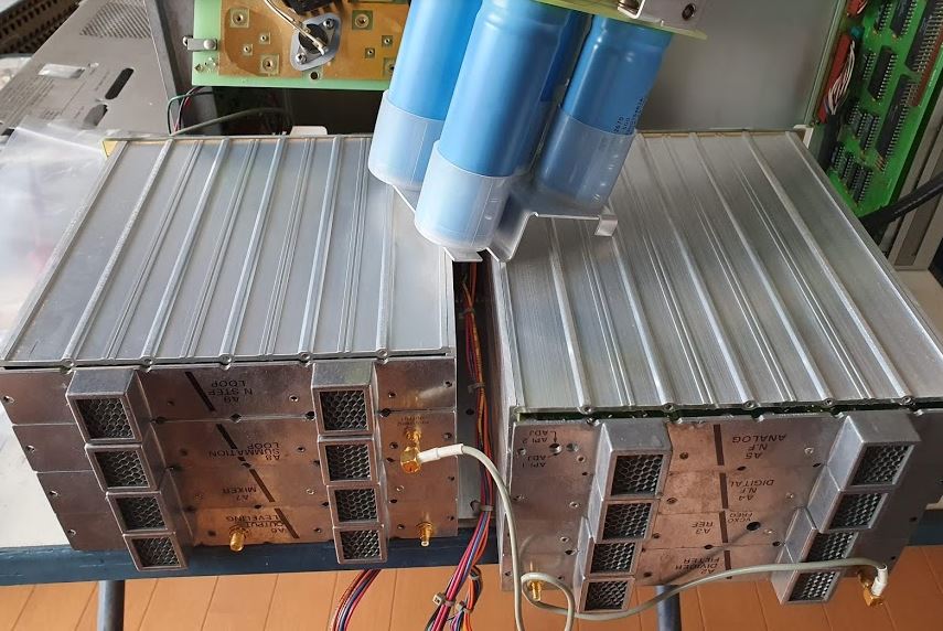
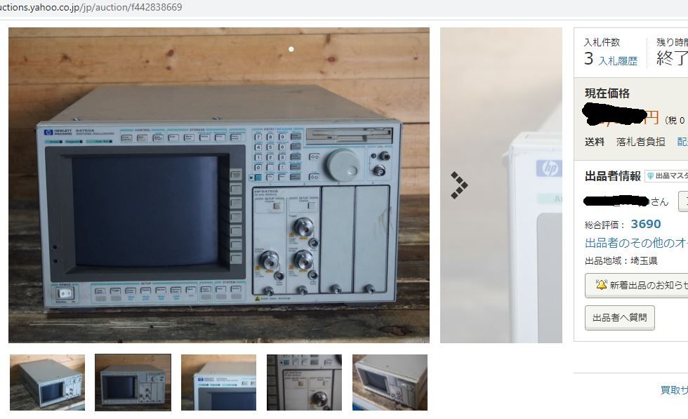
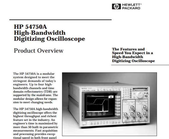
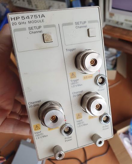
At the famous Yahoo auction, in Japan, I found this great instrument, a 54750A with a 54751A plugin. This is no less than a 20 GHz bandwidth(!!) sampling scope. I used to own one before, but have sold it some years back. At the time of introduction, these were the top instruments, in the 1995 to 2000 years. Still today, a 20 GHz scope doesn’t come cheap!

Normal issues with such unknown, non-working units are broken plug-ins, shot samplers, or other various difficult to fix issues. The samplers tolerate no ESD, and no more than 2 Volts! So please don’t let just any kid play with it. Not sure what happened at some companies in the past, when the engineer shot the 10 kUSD plug in… the whole unit traded for about 50 kUSD at the time, not too long ago.

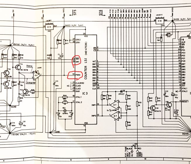
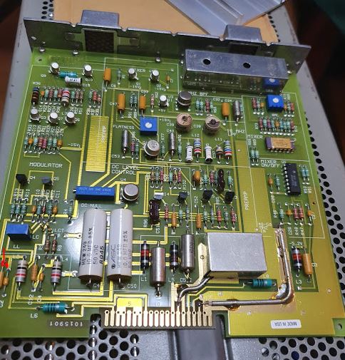
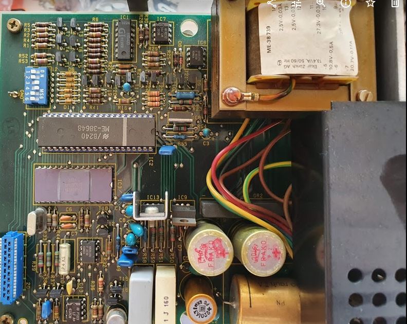
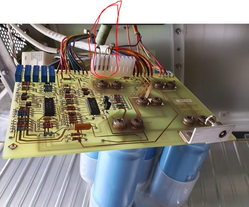
This unit, it just won’t power up at all. No sign of any activity. So I took out the plugin, and started troubleshooting. The power supply.

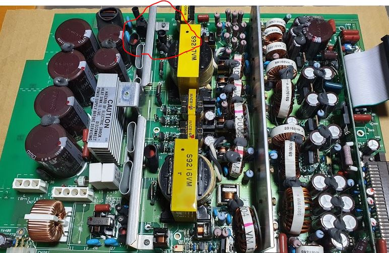
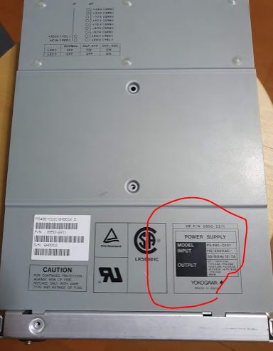
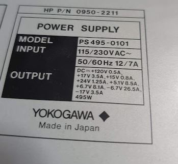
These supplies were purchased from YOKOGAWA, a really high end supplier, and there are protection circuits for all voltages, including interlocks for the fans! But this unit has no need for any interlocks, because there is absolutely no power.

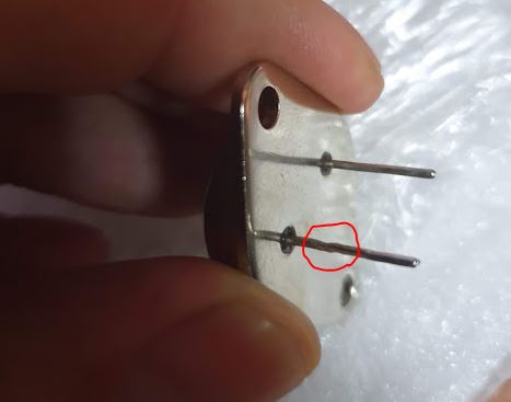
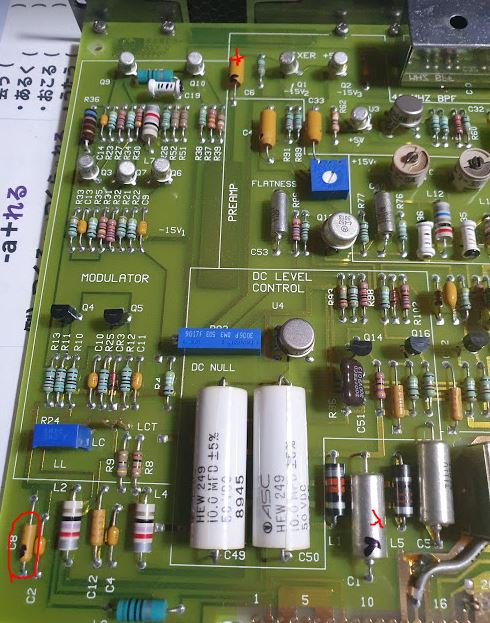
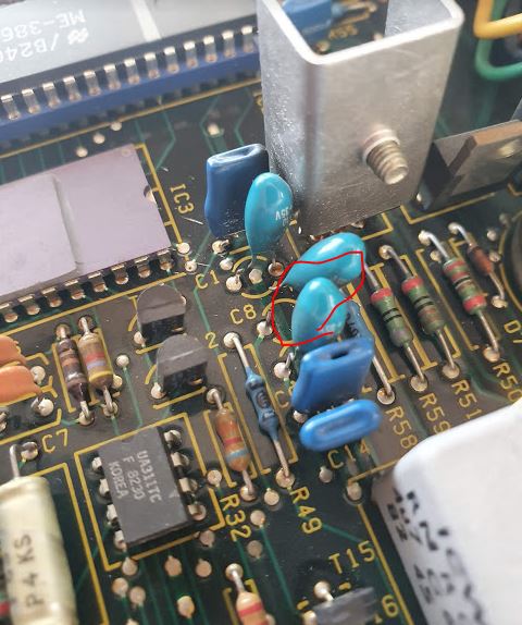
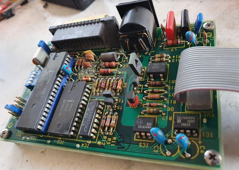
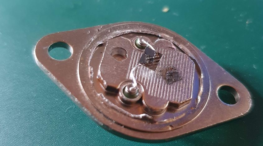
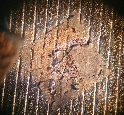
A little bit of examination shows discoloration and defective diodes.

The diodes overheated, because they are short. These are primary side diodes.

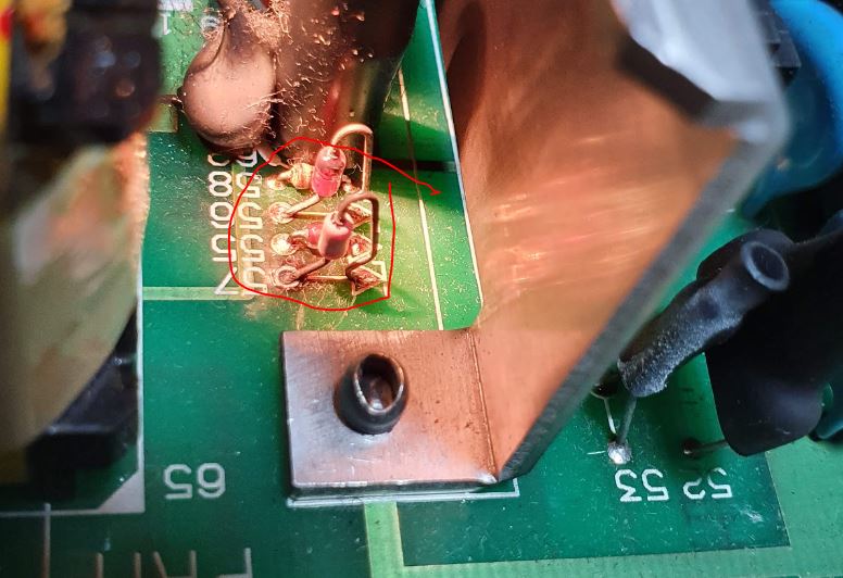
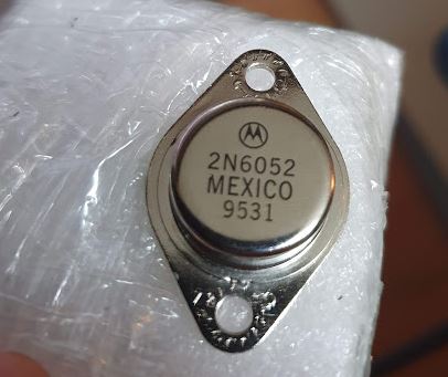
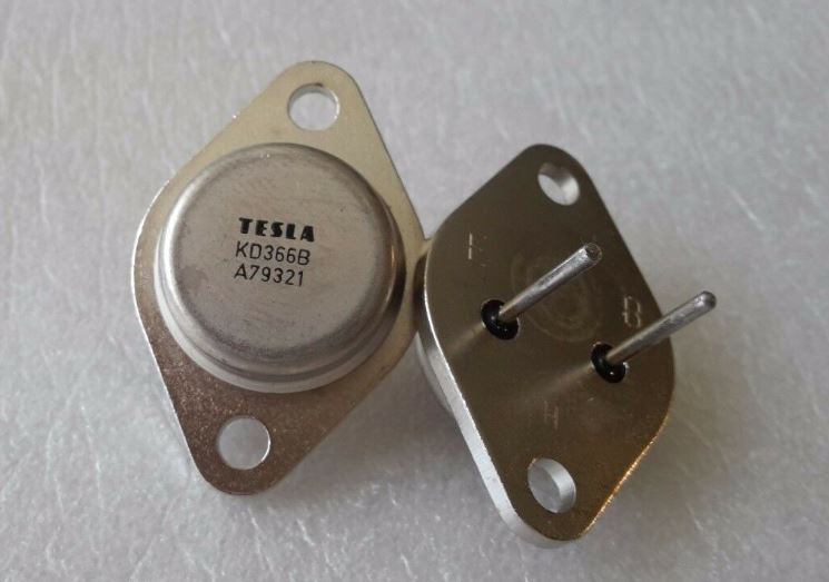
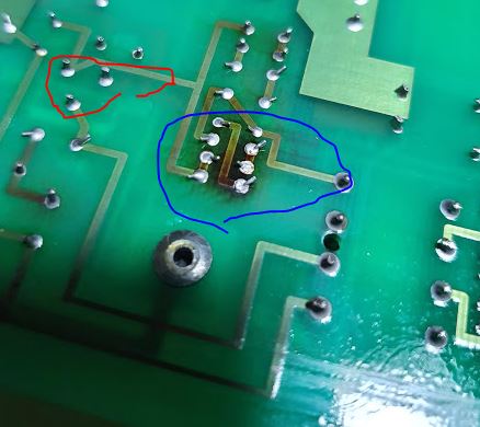
Also one of the transistors around this area of the supply failed. A 2SC3866 high voltage transistor, nothing too special, but none at hand at the moment!

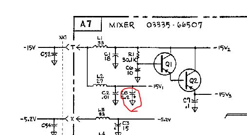
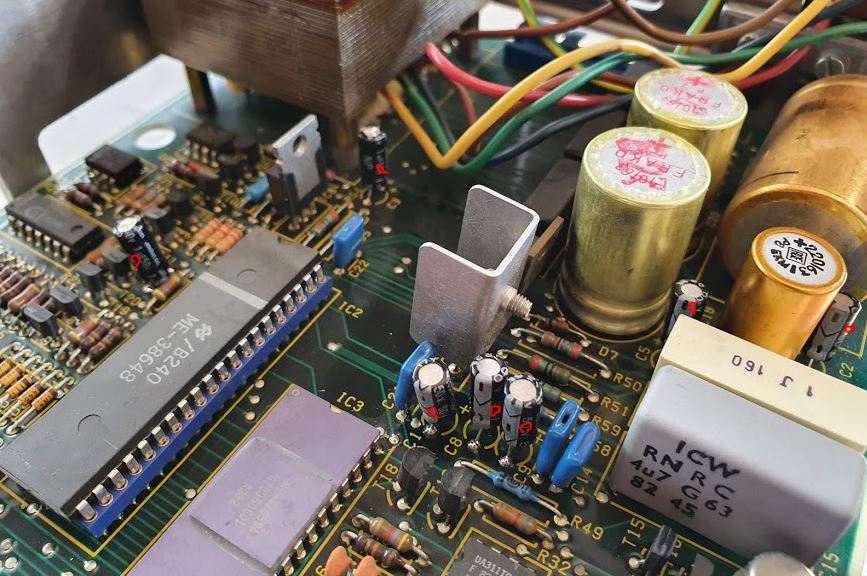
Some analysis of the circuit – it is clear that this is the startup (auxiliary) power supply that will start up the main power supply. Also the input current limiting resistors (2 units that have 22 Ohm and a 130 degC thermal fuse each) are blown, no wonder that there is no action at all.

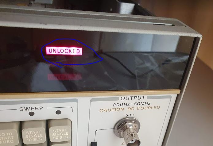
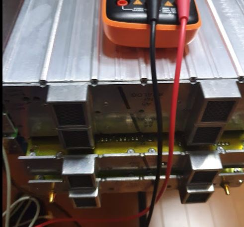
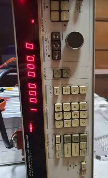
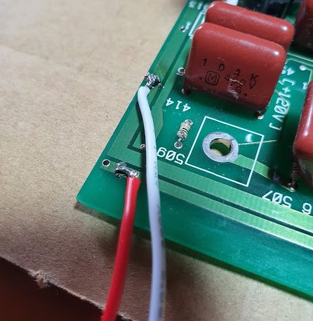
So I tried to connect an external supply, but there seem to be some other functions and details, so I can’t get the unit to start up. At least the red LED that indicates the auxiliary power, it is lit. But nothing else. Better not to proceed without schematics – which aren’t available.

So I have two options – wait to be able to go to Germany again, where I have a 54720A mainframe that has the same supply, and do some tests and investigations on that supply, or, see if there is a spare supply available somewhere. Kindly enough, a US enterprise offered a spare for USD 25, a great price!!! Plus 70 USD shipping to Japan…. Well, I purchased it and now waiting.

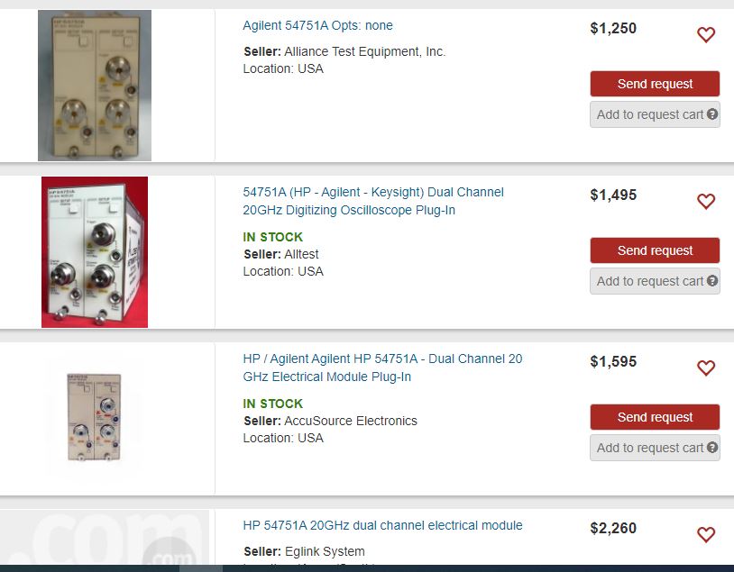
The 54751A module – even if the mainframe won’t work again, it is great find. These usually go for USD 1.5k, working condition. And I do have spare samplers back in Germany, in case it is a damaged unit (but as the mainframe has a power supply failure, I suspect that the module is fine, and that the unit was taken out of service because of the non-working power supply).

Some current offers…

HP 3335A Synthesizer/Level Generator: Unlock issue, soldering issue?

The recently fixed 3335A, it still has some issue with the reference input. From time to time, or when touching the BNC cable connecting the 10 MHz OCXO output with the reference input, the *UNLOCK* light comes on.

First I thought it has to do with the low cost and cheaply made BNC cables, but even with very good BNC connectors, the issue persists. So, let’s open the thing up another time. I don’t like partially fixed instruments – even though this error could probably be solved by just not touching the cable….

Fortunately, the BNC connector has a long cable internally, and can be disassembled without destroying the crimping.
Checking it, the center wire has no connection. Looking at it in magnification, it seems that only ever the very tip has been in touch with solder, but inside of the golden BNC center connector, there is no solder. So it is clearly a HP manufacturing issue, someone didn’t solder it quite right.

After soldering it again, with plenty of solder, and removing the excess, all is working well! Finally!

Force compensating precision balance: a few very interesting, very rare schematics

With the recent repair of a Mettler AE analytical balance, I never thought that the schematics would be available and obtainable anywhere. Maybe even the Mettler corporation only has some dusty copies in their Swiss secret archive. But, as luck would have it, a very kind reader provided some of the schematics to facilitate repair and understanding of the working principle.

At the time of the balance, like, 40 years back, it was still a challenge (maybe it is still challenging today), to build a mechanical system and ADC converters that are stable in resolution and drift to 1:10E7 counts and similar.

The basic working principle of force compensation and precision balances has long been known from the relevant patents, Sartorius, Mettler, Shimazu and similar. There is position sensor that can very precisely detect the position of the balance, to better than a micron. Then, there is a force coil, a magnetic system similar to a loudspeaker to compensate the force. Various levels and hinges may be involved. Then, there is a current regulation, a current reference, and a ADC to deal with the conversion to digital information. There are also normally temperature sensors to compensate temperature drift. Normally, the balance is continuously measuring the reference current and the coil current, and for best results, always leave it plugged in. Inside, there is some quite heavy aluminum case not only as an electrical shield but to avoid temperature imbalance. Accordingly, even when “switched off” by the front panel switch, these balances are actually internally on, doing their thing.

Key part is the position sensor. It works by a differential pair of photodiodes, and the total photocurrent is kept constant by active regulation (the left opamp), both diodes work vs. ground in essentially short-circuit current mode. Note that at the red point, the currents of both diodes add up (as total flux reaching the diodes) and need to cancel out the current from the 680 k resistor to 15 V rail. One diode, of course, has a resistor in the feedback loop of the right opamp (transimpedance amplifier) that will drive current through the 680 k resistor in its feedback loop to cancel out any differential current of the two diodes (to keep the negative terminal at virtual ground). More precisely, both diodes are keep at constant bias (short circuit) even if the photo current various or is unbalanced. Such setup has very linear response over several tens of micrometers. Rather than the BPX48 diode, you can use better Hamamatsu parts. Normally a small slit is used to illuminate the diodes, say, 30 um. You don’t want to make it too small, otherwise, there will a lot of light needed with associated heat and drift, and you don’t want to make the slit to wide otherwise sensitivity will be less. Certainly good to use a high efficiency light source like the SFH401-2 (15 degree emission angle, IR emitter).

The ADC, it works by an integrator, a reference current source (based on a LM399 high precision reference in some balances!), and a few current switches.

The magnetic coil current is simply regulated by a control loop that has some lead-lag elements similar to a PID regulator (otherwise such loop won’t be stable because of the nature of the electromagnet and phase angle).

Such system is integrated in a custom ASIC. Probably the best solution at the time.

HP 3335A Synthesizer/Level Generator: a good fake transistor? at least, a working unit!

Recently, I got a very nice but non-working HP 3335A, with a defective power supply.
After a little wait, the spare PNP power darlington transistors arrived. 2N6052, pretty general purpose power transistors.

The look very shiny and heavy chromium plated, I got 4 pcs, and two had some marks of screws, and 1 had irregular connection wires. Doesn’t look like a genuine Motorola, but well, it is no rocket science anymore to make PNP darlington transistors.

After installing the transistors (I checked the contacts on the board, they seem to be good), some quick test with the load transistor showed perfect regulation of the power supply both on the -15 V and -5 V rails.

With the module assembly connected, unfortunately, the -15 V rail goes up to about -3 V, by current limit regulation.

No other way to find out than by checking module by module. The 3rd last checked turned out to be the faulty one – A7 assembly, mixer.

A little shorted 2.2 uF cap…

At the far lower left.

Replaced it with a 10 uF ceramic multi-layer capacitor.

To check the quality of the transistors, I sacrificed one piece, and cut it open – seems very solid inside, with copper heat spreader, well-mounted die, good bonding wires. So even if it has not been made by Motorola, it seems like decent quality.

Now… doing a proper test…. several hours on, to see if there are other weak links. The attenuator at least is working, and the output is good!

Banana Muffin: sooo delicious, and we don’t add any chocolate

I use this blog for various purposes, including, not to forget the well-proven recipes and to make them available for your use, if you like.

This time, we have banana muffins. There are many recipes on the internet, but none that is really as easy as this one, and that works without a mixer or other equipment.

First of all, take about

5 bananas (large), or 6 bananas (middle size) – best some really ripe bananas.
120 g butter and/or margarine (I use 80 g margarine, and 40 g butter in Japan because butter is in short supply), unsalted butter of course.
4 eggs.

The bananas cut them up a bit and use a fork to make to uniform mass. Then mix well with the nearly molten (but not hot) butter and eggs.

Then, prepare a mixture of

300 g all purpose flour
1 package vanilin sugar, or some vanilla essence.
2/3 of a pack of baking powder, about 8 to 10 g
170 g sugar
1 little bit of salt

Mix all this well as a dry powder, or put it all through a sieve if you have.

Then mix the liquid mixture, and the dry mixture well and fill into muffin papers in their forms or trays. This will yield 20 pieces. Don’t overfill, form needs to be filled to about 6 mm below the surface only.

I am baking these in a professional deck oven, 180 degC upper, 175 degC lower temperature. For 25 minutes. Sure you can use other ovens at some similar heat.

After baking, you can enjoy these immediately after cooling. May apply some powdered sugar, icing sugar, as you like.

Oooh. So delicious.

Mettler AE 163 Dual Range Analytical Balance: Swiss Made equipment, in Japan

Regularly screening through Japanese auction sites on the lookout for some gems, I found a great AE 163 Dual Range analytical balance, completely non-working condition. No display at all. From the picture it looked like a rarely used clean unit (be careful when buying some old lab equipment, some might have quite some damage by chemical vapors etc.). I scored it for 7 EUR, great!! Plus another 20 EUR in shipment charges, but at least it was packaged very well and arrived with no damage in transit.

The specifications are better than most modern analytical balances ranging in the 3-4 kEURs, with 0.1~0.2 mg linearity, built-in calibration weight (accurate to 0.2 mg – very hand to recalibrate the balance after taking it to another place, or just to confirm that it is working fine), and these were the high end balances of the 80s, still in use today in various labs. I remember to use such balance during my time as a researcher at the University of Eugene, Oregon, a while back…

The balance has about 4 circuit boards, a display/keypad (an ingenious single bar keypad, easy to handle with gloves on, etc, without disturbing the balance), a control board that also has the main power supply, a sensor board for the force compensator, and a current driver board for the coil. These balances work by force compensation, i.e., there is a magnet coil that will compensate any weight you but on the balance by electromagentic force. And there is a pretty sensitive position detector (a light gate) to keep the regulation control loop going.

After some probing (there are no schematics unfortunately, but anyway, difficult to fix because there are mask-programmed controllers and custom ICs), found that one of the supply rails is down, shorted by some tantalum. 10 uF blue paint-dip type.

Decided to replace them all, including two 1 uF tantalums. Tantalums can last a long time, but some series tend to fail one after the other.

With quite little effort (also because of the nice serviceable design of the unit), all working again.

Here is a closeup of the force coil, it should have a coil and a strong magnet inside.

The light gate of the position detector.

These will also need to be replaced, 3n3 Y-rated capacitors, getting brittle after 28 years…

The balance also had an add-on, a serial interface. The circuit is quite complicated for its function, using mask-programmed CPU, but that used the be the most reliable technology at the time (and still working today).

Also with that interface add-on, replace the tantalum caps, and the Y-rated caps (mains is fed-through to the balance from this add-on module. Not sure why they added another set of Y-caps, as there is no mains related circuitry inside (2n2 value caps).

HP 3335A Synthesizer/Level Generator: a marvelous piece of engineering and precision

For several years I have been looking for a HP 3335A, which is probably the most precision level generator that is available. Some of the more recent devices struggled to keep up with the performance, so the 3335A is still used in some calibration labs, and has thus been quite expensive even until now. This time, in Japan, I found a non working unit for 10 EUR (!!!) including a precision OCXO reference. It is a very clean and late unit (about 1991), but not showing any signs of operation.

The front panel, it is pristine, with no scratch or anything. Maybe a rarely used instrument from some remote Japanese cal lab or university.

The key part, the attenuator, it is a marvel of engineering, don’t touch it without reading first the repair instructions.

The 1990 HP catalog entry, 0.05 dB absolute level accuracy, 0.07 dB flatness. Such performance did not come cheap, 13000 US dollars in 1990….

To achieve the frequency resolution, a fractional N loop was used, it is one of the first instruments that used such PLL technique.

The RF boards are in two metal enclosures, pretty heavy extruded aluminum.

After some tests, pretty obvious faults – the -5 and -15 V rails are dead. There is unregulated voltage present, so it must be something with the regulators, a classic design with darlington pass transistors, and opamps to regulate the voltage and current.

The strange thing, with the modules disconnected, the rails come back to the precise voltages.

Made a plug with a 27 Ohm resistor to load the rails a bit, and, they immediately drop to near-zero. Seems there is not enough capability to drive current.

Took out the pass transistors, and tested these by driving 1 mA of current – but no amplification or anything. Open circuit.

Opened up both transistors, and both have the same defect – the die is not attached to the case any more, somehow, time, heat or something destroyed them (overload is unlikely, because the current regulation loop and foldback is working).

The original parts 1853-0415, power darlington, seem to be equivalent to PMD13K60 of a mysterious Lambda semiconductor company.

There are NPN and PNP complementary sets available. It is a fairly standard darlington power transistor.

From the web, we get another proof, there HP installed the parts with the original part number, rather than re-labeled to HP number.

The replace, the 2N6052 seems to be a good replacement. So I ordered a few – waiting.

As a backup, also ordered some KD366B which seem very strong and well fabricated.

The NPN transistors seem still Ok, but who knows, they might have the same manufacturing defect, so I ordered some BDX87B (which are ST devices universally compatible with various NPN power darlington transistors up to about 100 V; nowadays, all these power darlingtons seem to have the same die inside).

Now, let’s wait for the transistors, stay posted!