HP 4192A LF Impedance Analyzer: some trouble in the signal chain

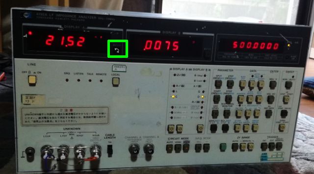
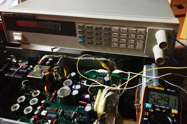
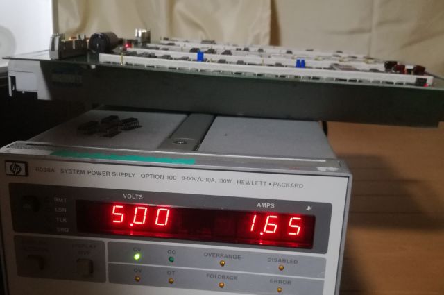
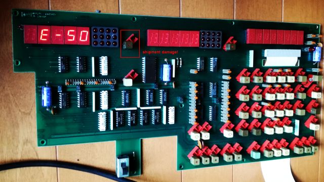
With some success, and power supplied at proper voltages to all assemblies, we can get into the inner workings of this marvelous unit. There are issues, all kinds of UCL messages and E-07 during calibration. Connected a 1 kOhm resistor as a test device, and played around with the ranges and frequencies, and some luck – at 1 kHz, and with manual range selected, I do get a proper measurement (but not in the other ranges), at higher freuquencies, no measurement possible, the bridge is not balancing.

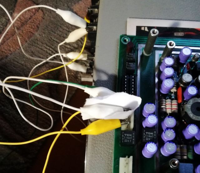
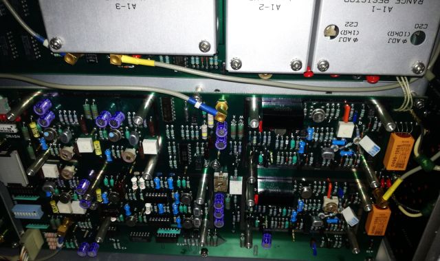
So, let’s take it step by step. First we need to check the source assembly, A1, or part of it – quickly found out that the supplied voltages and source resistor switching (by mechanical relais, therefore it is a good place to check – but difficult to fix, because there is all kinds of magic around these relais to eliminate parasitic capacitances – you can’t just put in any ordinary spare part). All is good with the source assembly.

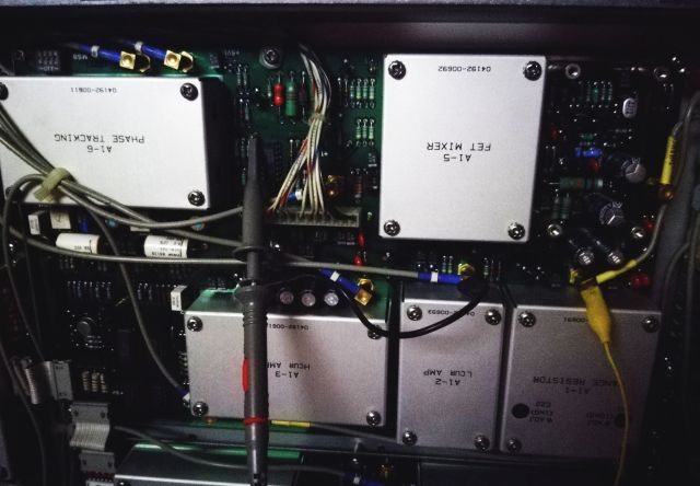
Also the inital stages of the receiving section and the mixer, working fine. These circuits are part of the so called process amplifier, A11 assembly. The whole input circuits, please be careful, there are many precision parts and FETs and expensive things – don’t damage it. And it is pretty complex, so don’t get lost.

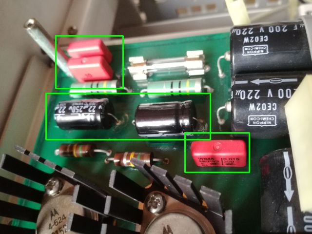
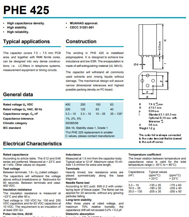
Along the way, an interesting part, a RIFA precision PHE425 cap.

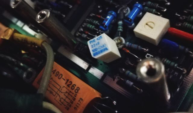
The “F” in 22nF is not actually Farad, but the tolerance denominator of Rifa, meaning, 1 % tolerance. The caps have very good data, very low drift over time, and a very low voltage and temperature coefficient. Maybe I will consider these for own designs, filters, and so on.

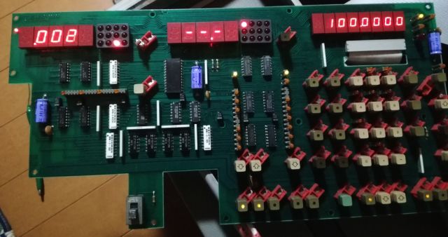
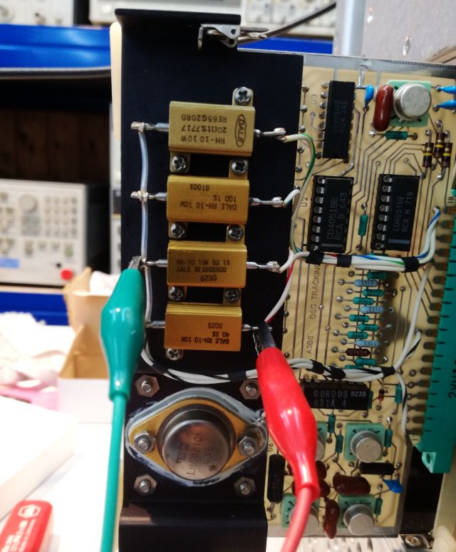
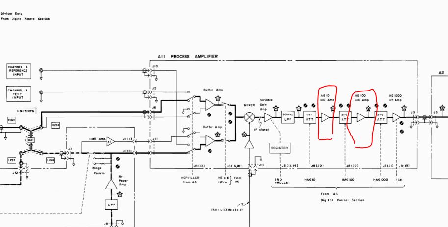
Testing, and testing again: found an issue with the IF amplifier – it is not switching the amplification properly, it is overly amplifying the signal (locked in x10 mode). No wonder it doesn’t work at high frequencies as it will saturate the following circuits.

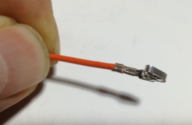
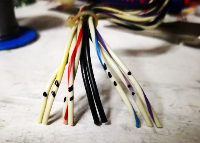
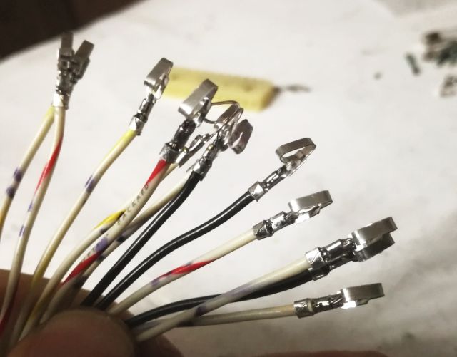
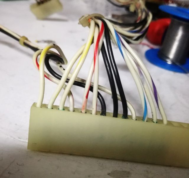
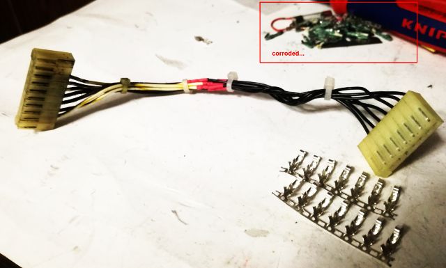
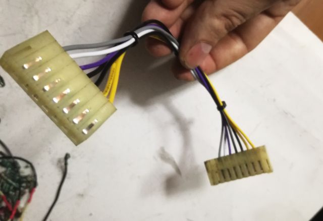
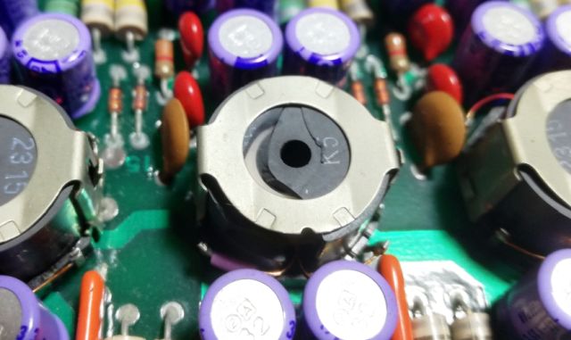
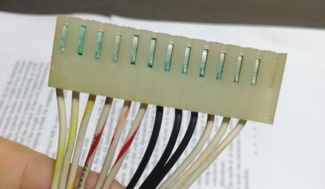
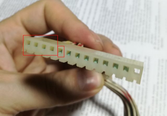
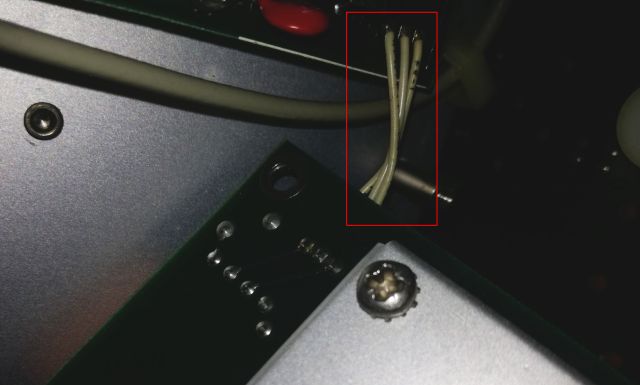
The A11 board, it is not as service-friendly as usual, because it is connected to the A1 board by 3 wires that are soldered to the board, in a narrow space (no plug!).

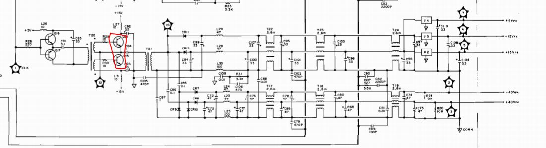
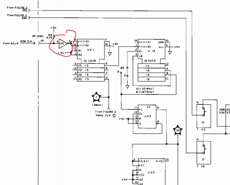
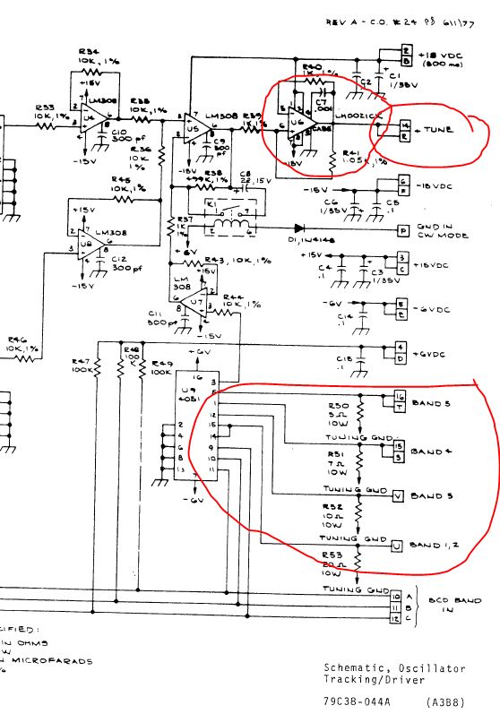
In the block diagram, you can clearly see the x10 and x100 amplifiers.

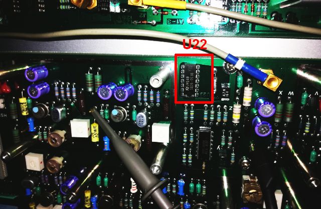
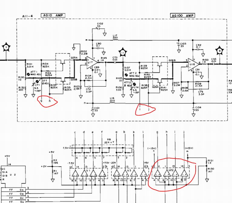
These are controlled by a quad comparator that is set by the controller assy.

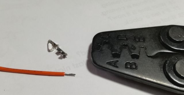
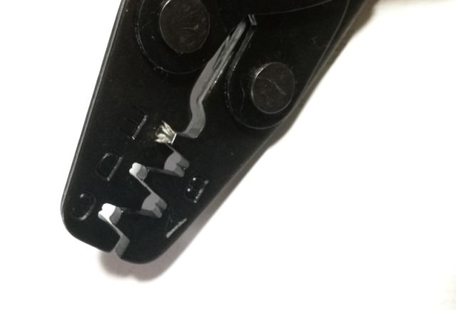
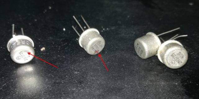
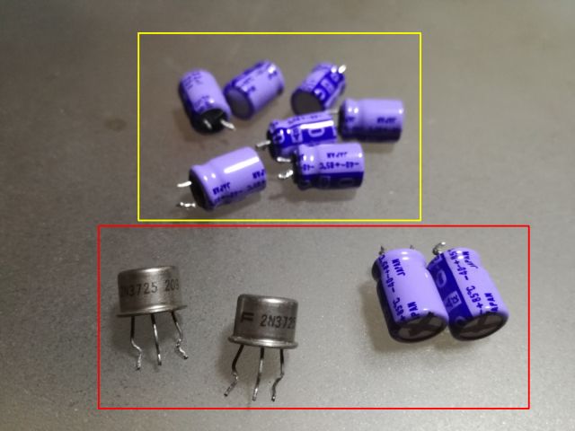
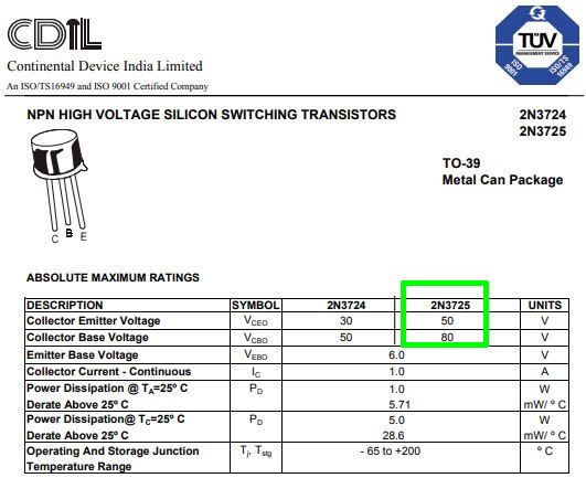
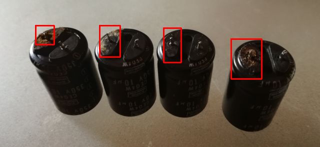
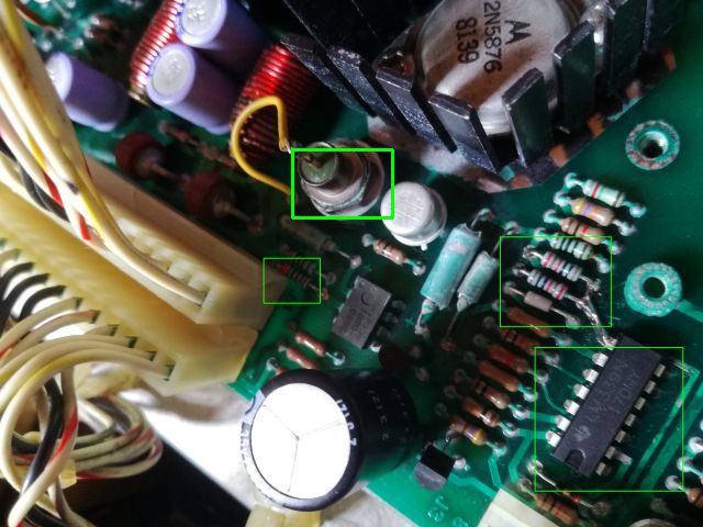
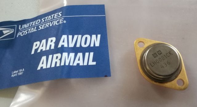
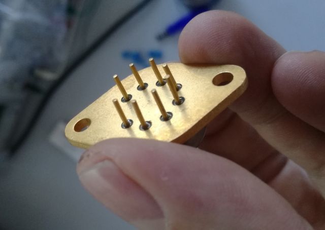
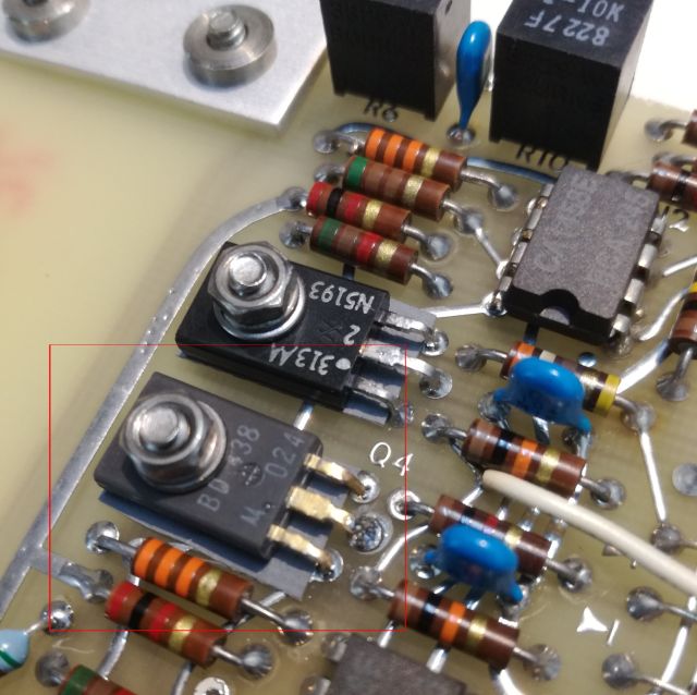
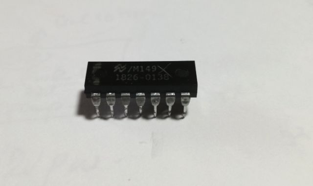
Some LM339’s are in stock here, it is one of the most essential parts to have in any electronics workshop. The LM339 is the equivalent to the HP 1826-0138. It is run at over 30 volts supply (-16 to +16 V), maybe it got damaged during the power supply failure and some related surges. But the 1826-0138 HP parts are also known for some age-related failure, at least I have already replaced a few others in HP instruments.

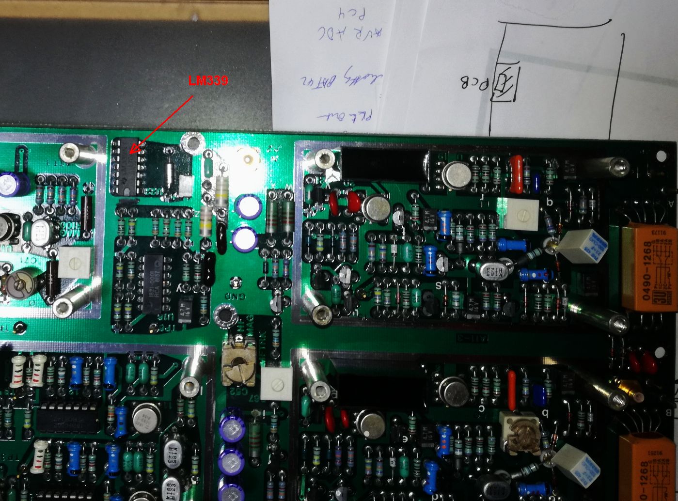
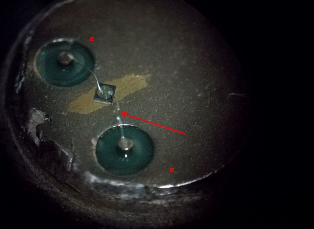
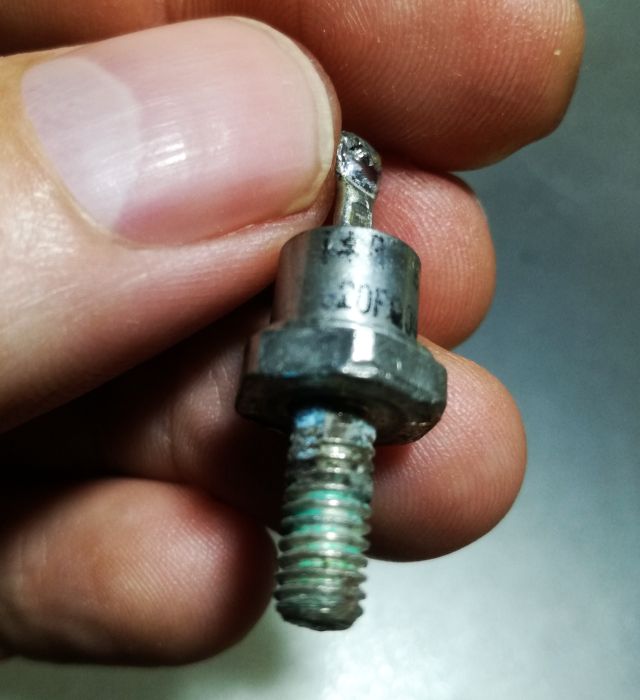
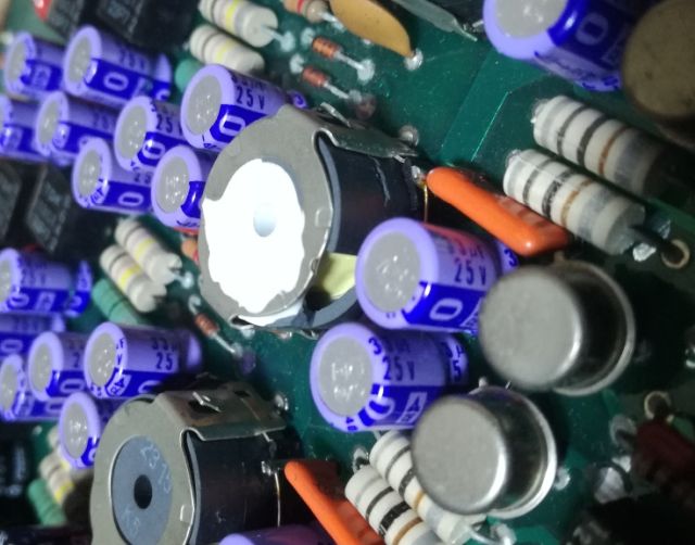
The bad part – causing all the trouble.

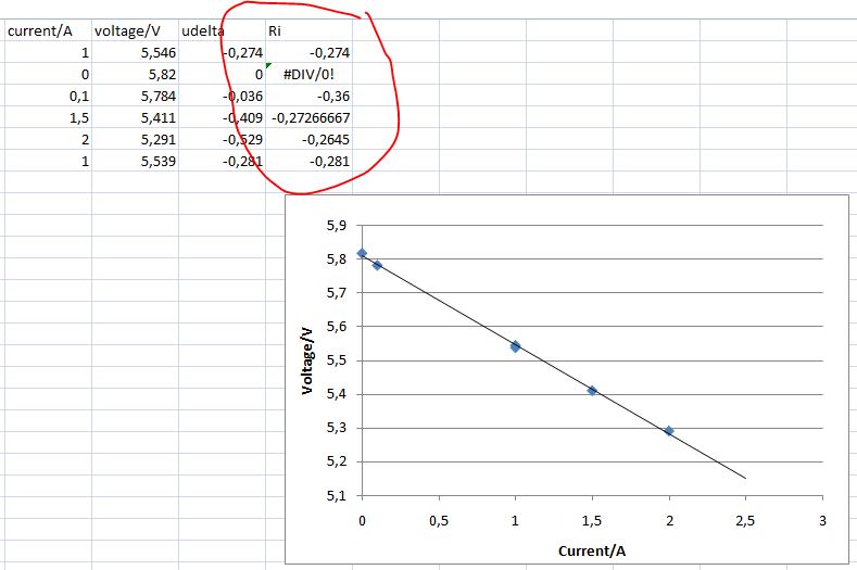
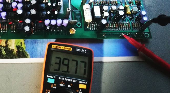
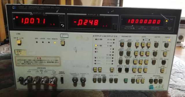
Quite some extensive tests later, I decided to put the instrument back together (many of the shields still removed), and had it run for a day with no problem. Self test and calibration is working at all frequencies. Adjusted the phase balance, the amplifiers and attenuators according to the manual’s instructions. Adjusted the power supply after due warm up. Not much adjustment needed. The bias supply, it is as good as the test equipment I have here, will need to do some tests later in Germany with some better voltmeters.

Some test measurements – using a 1 kOhm, and a 22 nF capacitor.

Also, still needed from the stockpile of HP spares back in Germany – a push button cover (the switch itself is working).

Crimping Molex Contacts: 3.96 mm KK Style, new capability add to my workshop

For year I have been using various Molex style connectors, 2.5 mm, 3.96 mm, and so on, but never by crimping own contacts. Criming is a special art, and if not done properly, it can cause all kinds of reliability issues. So I usually purchased pre-crimped wires, and just assembled them for contact blocks. In other cases, I just used regular pliers to mount wires to contacts, and soldered them in (best, to pre-tin the wire, then mount it in the contact with small pliers, then solder it in – this will result in a very reliable connection. Also, never use low quality wire, only full copper core, heavily tinned wire, UL 1007 or similar.

But why not try to crimp contacts ourselves and add a new capability to the workshop? So I went ahead, and ordered a low cost pair of crimping pliers, EUR 12, not bad.

It made it from China to Japan very quickly, delivered by a friendly postman (here they are very friendly). That’s the tool: quality looks quite OK, and the steel is pretty hard. Sure this is not a high throughput production tool – I am looking at a few 10s of contacts every year, not 1000s.

Step 1, remove the insulation from the wire, and get the contact and pliers ready.

Step 2, insert the contact in the pliers, and close it until flush (don’t apply much force).

Step 3, insert the wire, and crimp the inner connection. Don’t get any of the insulation caught up by the crimp. It is a bit inconvenient to get the contact out of the pliers, probably will make a special tool for it (a U-shape bent piece of steel sheet metal to push out the contact).

Step 4, Inspect the inner crimp. Use a magnifier if necessary (make sure no plastic and insulation got into the crimp area). Pull on the wire, it must be firmly held (a properly crimped wire can’t be pulled out by any reasonable force).

Step 5, slightly close the insulation crimp using the tip of the pliers.

Step 6, establish the insulation crimp.

Step 7 – It’s ready. Inspect. Carry out pulling test.

HP 4192A LF Impedance Meter: power supply, and power distribution fixes

Finally, some spare parts arrived and now I can proceed with the repair of the HP 4192A power supply and power distribution cables.

First, the floating power supply. The main defect has been fixed, and I have been waiting for new-old-stock (NOS) 2n3725 transistors from a very reasonable Taiwanese dealer. These 4 parts arrived. All different case and vintages. Note that one of the transistors has a black pencil mark.

These parts didn’t look all too trustworthy – at least they are no fakes. So I went ahead and tested each transitor. One found defective, no signal on its base. Why is that? So I took a look inside, and indeed, the base bonding wire is blown. Judging from the ends of the bonding wire, it blew because of overcurrent. This is the part that had the pencil mark – maybe the former owner had already marked it as “defective”, and somehow the transistor made it to the trader.

Anyway, we only need two transistors to fix the assembly. And keep one as a spare. A quick test shows – no issues with the floating power supply, all stable and these transistors are not running hot.

Next step, fixing the wires affected by the leaking electrolyte, especially, the Molex contact – they are all brittle, and have a green corroded layer on the surface.

Cutting the wires, there is even some slight corrosion inside, soaking up into the wire. Therefore I decided to solder the contacts, rather than just crimping the contact. This way, I can see if the solder is flowing, which will ensure a good contact.

Seems like a huge task to rewire all these connectors, but if you have a steady hand and some patience, it won’t take more than 1 hour.

Make sure not to mix any wired – it may destruct the 4192A beyond reasonable repair. So I took picutures, and notes, and marked the wires additionally.

The rewired connector – all shiny contacts!

Further on to the next issue. The rectifier diodes of the 5 V digital supply. My original plan was to install a Schottky double diode.

While one of the original diodes was non-working, the other one looked good, at least electrically. Upon disassembly, it turned out to be quite bad as well:

Then, I remembered a pair of SD 41 diodes at the bottom of my spare part pile (a board from a HP 8662A power supply), so I dediced to go forward with a 1:1 repair – fitting diodes of the same case rather than a modern part (and, I found good SD 41 diodes in Germany at low cost, so I have ordered a few as spare parts).

The typical current needed for the HP 4192A – about 2-2.5 Amp for the 5 V digital supply rail. With the unique nature of the 4192A CPU board, I didn’t want to risk anything, so I put the supply to a good test with an electronic load. And it easily can provide 2 Amps, at the right voltage.

The digital supply has no regulation, the output voltage will depend on the load. But how strong is this dependence – any risk to drop out of the 4.75-5.25 range that is prefered by most TTL logic?

An easy thing to establish with the electronic load – see diagram below. Internal resistance is about 0.27 Ohms, it is quite stable, slightly at the high end of the range.

After all these repairs – let’s put it to a test. Still, all is in pieces, but, the 4192A is running through the startup tests with no problem and showing activity! So it seems the EPROMS are good, and chances are, we can get it back to work.

Celebrated a bit too early – some issues when moving the board-touching the cables to the CPU board. Probably, contact issues with the corroded wires.

The digital supply connector was very close to the leaking batteries, so the wires and connectors were damaged so much that I first had to cut about 8 cm of wire, to get to some copper that would accept solder. Not good, but I thought it would work for a temporary repair, which it did. But it also caused the unrealiable operation, because the corrosion extended all the way to the CPU connector.

Easy fix – just rewired the whole thing, again, taking extra care not to mix any wires or causing any shorts. Wire is AWG22, UL 1007 PVC insulated. All the contact were crimped and soldered to make sure there is good, realiable contact.

With this “new” cable, no sensitivity to touch any more, the CPU board is now getting stable power.

HP 4192A LF Impedance Meter: Isolated power supply fixed

Working through the guts of the 4192A, I tried to operate the A8 assembly, which has several +-15 V isolated power supplies (for floating voltages, etc.), and a +-40 V bias supply, set by a pretty cerdip DAC.

Basically, the assembly consists of a set of switched power converters, converting the +-15 V input, to isolated +-15 V output. Running at about 900 kHz to 1 MHz.

The assembly is double shielded, to interference with the impedance measurements. It has a set of coils and capacitors, a number of parts! Definitely not a cheap unit to build at the time.

The issue – when connecting it to the 4192a power supply, it loads down the +-15 V rails, and the power supply assembly A7 of the 4192a soon goes into shut-down. Not a good sign.
Analyzed the circuit by touch, almost burning my finger – the two main switching transistors of the 4th supply are glowing hot!

Did some measurements, and the transistors, as well as two capacitors are dead. The other capacitors, I removed them because you never know, and better to fix it now than later.

Interestingly, the capacitors HP selected were 85°C rated, I decided on some Panasonic EB series, 105°C rated, low ESR-long lifetime caps. Hope these will last another 30 years of occasional service.

The transistors – difficult to find good substitutes. I believe some other reasonably high current NPN fast transistors like SS9050 or similar would work, but I don’t want to take chances and found some new-old-stock 2N3725 on eBay. Only it will take a while for these to arrive in Japan!
For the time being, I desoldered the working transistors of the #3 supply, to get the #4 supply going for the tests.

Surprisingly, one of the transformers has a damaged pot core, K5 ferrite, difficult to get. Strangely, there were no loose pieces inside the shields, and no traces of earlier repairs. Can it be that HP fitted a slightly defective transformer? But as the unit is working and outputting plenty of power, the core should be good enough.

To fix it, or at least make sure that it is not rattling or desintegrating any further, we have a choice of epoxy glue, super glue, or silicone. I decided on the latter, a 704 type head conductive silicone. It is available really, cheap, and it is good stuff, because it can be removed later without destroying the coil, should I ever come across some K5 pot cores.

All fixed and stable.

A quick test – powering from a current limited lab supply (about 80 mA on 5 V, about 0.11 Amps on +15 and -15 V with no load are needed for the A8) to avoid destruction.

Fortunately, the A8 assy is working again. I didn’t test the DAC, but no reason to believe it would not work.

Now just waiting on on the 2n3725A transistors, and then, it can be all put togethers with many screws and pieces of shielding metal.

HP 4192A LF Impedance Analyzer: some issues fixed, more unveiled

After a quick trip to Germany (and with a set of spare parts in my suitcase), I directed my attention to the sick 4192A again.

(1) First, the A7 power supply assembly. Fixed the defective signal diode, and ceramic capacitor. Discovered that the line frequency signal is not working, and that the 5 V supply (analog section) linear regulator isn’t regulating, but passing through about 6 volts. Also noticed that the digital 5 V supply is not working (running at 2-3 volts).

(2) After about 20 seconds of operation, there is some smell around the A7 power supply assembly. The input caps (10 uF, 350 volts) running hot.

(3) No display at all. Is the controller assy dead? Or the EPROMS corrupted?

Let’s tackle it step by step.

Fortunately, we are not alone here, the same instrument had similar issues elsewhere – seems the NiCd batteries weren’t fit for the purpose, and have all leakage issues, as can be seen in below screenshot of a Japanese blogger.

Unsoldered the 10 uF 350 V caps of the A7 power supply – all the positive connections are leaking. Fortunately, not as corrosive as the NiCd electrolyte.

Strangely, HP fitted 85 C capacitors, rather than long life types.

On the picture you can see the temporary fix with some capacitors I had handy. And, you can see the Y-rated capacitors (15 n) RIFA cracked capacitors replaced by WIMA brand new parts.

For replacement of the 10 uF Chemi-Con we will use CFX series capacitors.

These are rated for quite severe ripple current, which is necessary because that’s their purpose in the A7 circuit.

Of course, 2 parallel capacitor 10 uF will have better ESR than a single 22 uF, but fair enough for test purposes.

The digital supply, surprisingly, has no regulation, neither by linear nor by switchmode action (the switchmode circuit is regulated by an independent sense winding on the transformer (running at 29.5 kHz).

The digital ground is connected to analog ground by a 10 Ohm resistor for noise isolation. Other than that, the circuit is rather simple and quickly found the defective part – surprisingly, one of the Schottky rectifiers, a 20FQ040 diode. Maybe it overheated, or it failed just because of age.

For its time, 1980s, it is a respectable diode, with very low forward voltage.

Unfortunately, replacements in DO-4 bolt-mount style Schottkys are very expensive and hard to get. Maybe there are some back home in Germany, in the junk pile waiting to be desoldered, but not sure about it, and no such diodes here in Japan. Anyway, after some measurement, the current of the digital supply will be somewhere around 2.5 to 3 Amps, not too much, for any common switchmode supply rectified diode. Decided on a SBL3040PT. 3 Amps at 0.2 Volts will be less than 1 Watt of dissipation, say, about 40 K temperature rise of a SBL3040PT double diode (such packages have about 40 K/W junction to ambient thermal resistance, probably I will fit a small metal part as heatsink (the existing heatsink may be used after drilling a mounting hole…).

Another issue fixed, a corroded spacer for the 5 V analog supply voltage-limiting Zener (a power Zener, still good!). The spaced could have been cleaned, but not worth the hazzle, so I machined a new one from aluminum alloy.

To the mains sensing and synchronizing circuit – some probing with a scope showed that the U1 comparator (a HP numbered LM339) didn’t work. Replacing it was no easy task, because this area had been affected by the NiCd electrolyte, rendering the solder pads difficult to desolder. Scratching off the corrosion layer from the solder with a screwdriver helped to get some contact with the head, and to finally desolder.

Further probing also showed a few damages to resistors, the wires had come off the main body (seems the corrosion damaged the weld between the resistor case, and the wire).

A quick test – there is a clean sync signal! About 120 Hz, double the mains frequency in this part of Japan. Perfect.

With these basics fixed (except the digital 5 V supply – still waiting for delivery of the diode – just fitted a temporary diode for test purposes), let’s have a look at the CPU board, which is a marvelous piece of engineering, with may TTL, EPROMs, RAMs, etc. – let’s hope we don’t need to fix this complex assembly.

Checking the clock and reset lines – no clock present! After some study of the manual, I understood that the CPU clock is generated from a 20 MHz signal, from the 40 MHz VCO and reference frequency assy. Why is there no 20 MHz? Easy answer, the referency assy has no power except -15 V.

Reason: corroded Molex connector, and broken contacts within. Not easily seen from the outside, but clearly, there is no contact.

Fixed the contacts, at least a few (and ordered more!), and voila, the 20 MHz and 40 MHz are back. No issues with any of the main counters (e.g., keyboard and display scan), good activity on the address bus, etc.

For proper tests, removed the CPU/controller assembly A6 from the unit, and powering it with a lab power supply, to make sure it gets stable power.

After all this, quite some relieve! The unit is starting up, at least as much as it can be told at this point (all the analog circuits disconnected from the A6 controller board – need to first fix their power connections). The startup passes all the RAM and EPROM tests, great! And finally stops at E-50, which means, it can’t find the line sync frequency – which is no surprise, because this signal is currently disconnected.

Next steps will be – (1) Fix the Molex connectors. Quite difficult because these are crimp connections, and the wired have some corrosion making them difficult to solder. (2) Finalize the A7 repairs – the 10 uF capacitors, the Schottky for the digital supply, test the digital supply. (3) Then proceed to the start up and repair-adjustment of the analog circuits, and synthesizer section, many, many, complex circuits, but these don’t have any visible corrosion or damage. Fingers crossed.

Micro-Tel SG-811 Swept Signal Generator: a hot (and golden) driver

Suddenly, my SG-811 microwave generator started to play up, running hot, and then, stopped working with power supply failing. Too bad! Fortunately, the Micro-Tel power supplies have a fairly consistent design for all their various instruments, and I have fixed already several of them, so it will be an easy task. In this case, just needed to replace the main transistors to get it working again (MJ12002 replaced by BU208A, which are much more easily available). But switching on, I immediately noted that something was wrong, too much heat and current around the oscillator control board. This board has a LH0021CK power (1.0 Amp) opamp that is driving the tuning coil of the YIG oscillators. The part seems to be shorted out.

Looking at the schematic, there are current sense resistors for each band, with the sense wires switched by an analog multiplexer.

The LH0021 are not quite rare, but expensive – fortunately, a kind guy from the US offered a pair for these on eBay, NOS or used, for a reasonable price. And some weeks later, they made it to Germany.

These are really nice parts, all gold plated and solid pins.

Replaced the LH0021, and the SG-811 is basically working, but still too much current on the LH0021. What is going wrong? Turns out, there is a oscillator control board inside the RF unit, which is switching the coils depending on the band selected. Probing around, this doesn’t seem to work, because one of the coils, band 3, stays energized all the time.

Easy to find the troublemaker – a shorted switching transistor, a medium power PNP, 2N5193. These 2N5192 are not very common, so let’s do a search for similar parts in by basement archive of obsolete parts – and, in fact, there is a bin of BD438, including a note about their characteristics, and a not from the former owner (a generous old man who didn’t need any electronic parts any more, and had several lifetimes’ worth of supplies).

With the RF unit open and the board pulled out, it’s a good idea to check all the transistors and diodes, and in fact, another one found shorted as well (not a tuning switch, but the main power for one of the oscillators).

With both of these transistors replaced, the SG-811 can be put back into service. Didn’t take all that long to fix, not much longer than to deal with repair quotes, shipment, and other hazzles when repairing more modern units.

…plenty of power, up to 18 GHz…