3047A Phase Noise System: the revival

For quite some years I have been dealing with temporary setups for phase noise measurement, mixers, amplifiers, analyzers, of all kinds. For the more noise sources, direct measurement with a good spectrum analyzer is rather straightforward, but in most cases, dealing with rather low noise sources here, and often, at rather high GHz frequencies.

Various techniques exist for reasonably accurate phase noise measurement of low noise sources, lately, at least in the <100 MHz region, correlation type (sampling) methods are used, and these instruments are great, really fast, and a good choice, if you have the funds and want something new and fancy. With all these choices nowadays, for many years, the HP (Agilent, Keysight) 3047A and 3048A were the gold standard for phase noise measurements (along with some Wenzel instruments). And, even better, the software at the time was written in BASIC, with all the source code available - so at least you know what it does and how it works. 3047a code

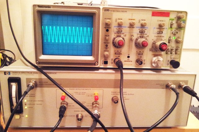
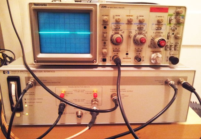
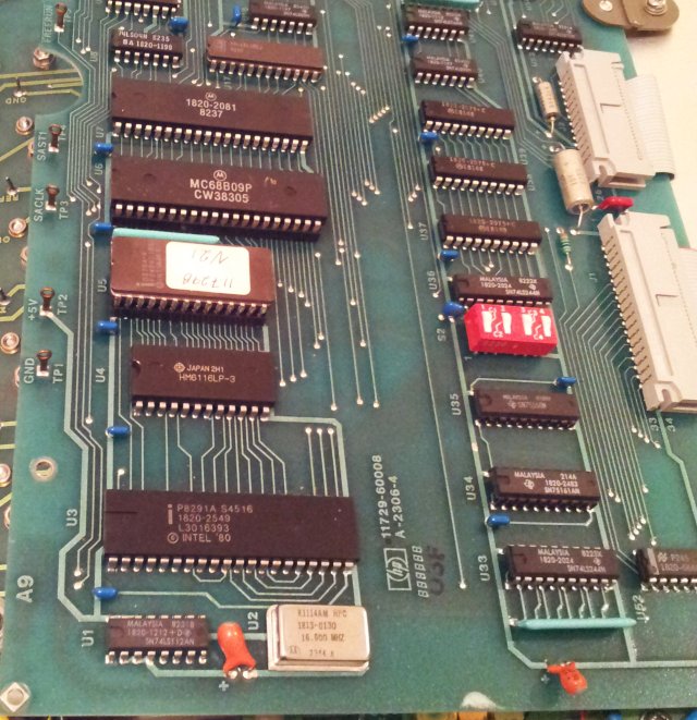
After scoring two of the 35601A units for a handful of dollars, time for a revival. With the old software no longer usable on current systems, some hours were spent to adapt it modern times. In the meantime, most of this software, at least the essential parts, have been implemented in C (still needs to be cleaned up, if you are working on a similar thing and need it urgently, let me know).

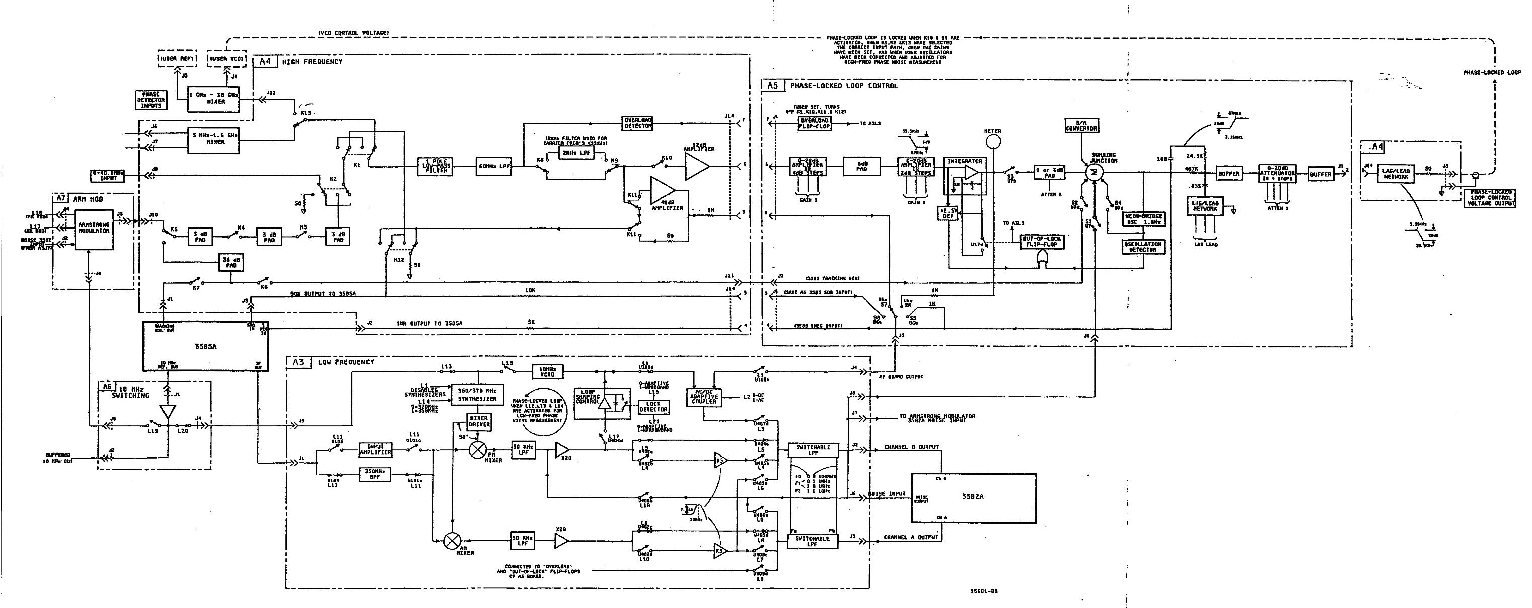
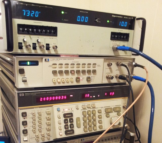
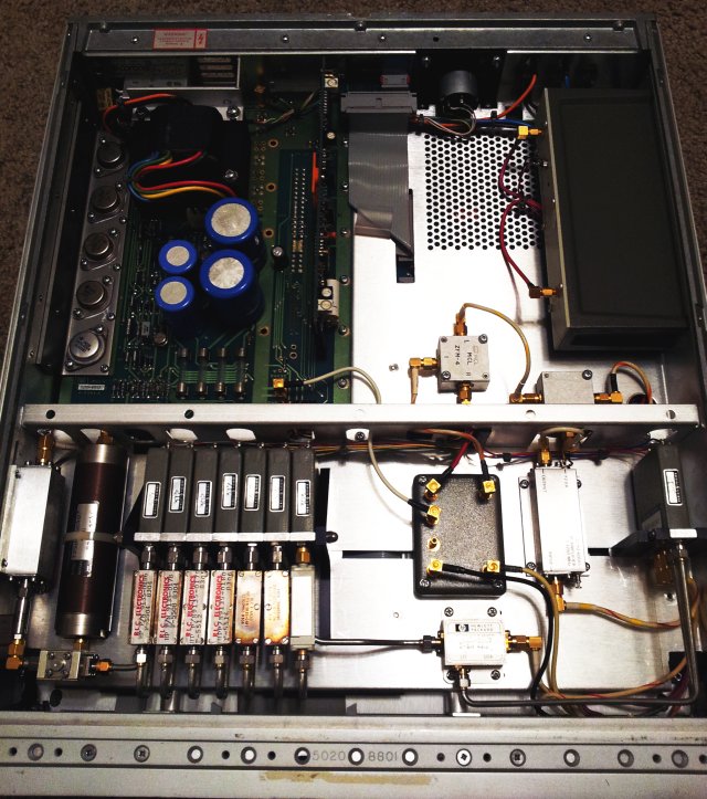
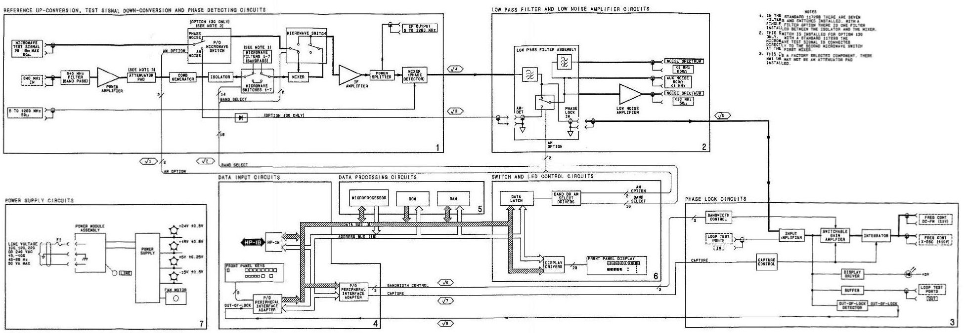
This is the general setup:
3047a scheme

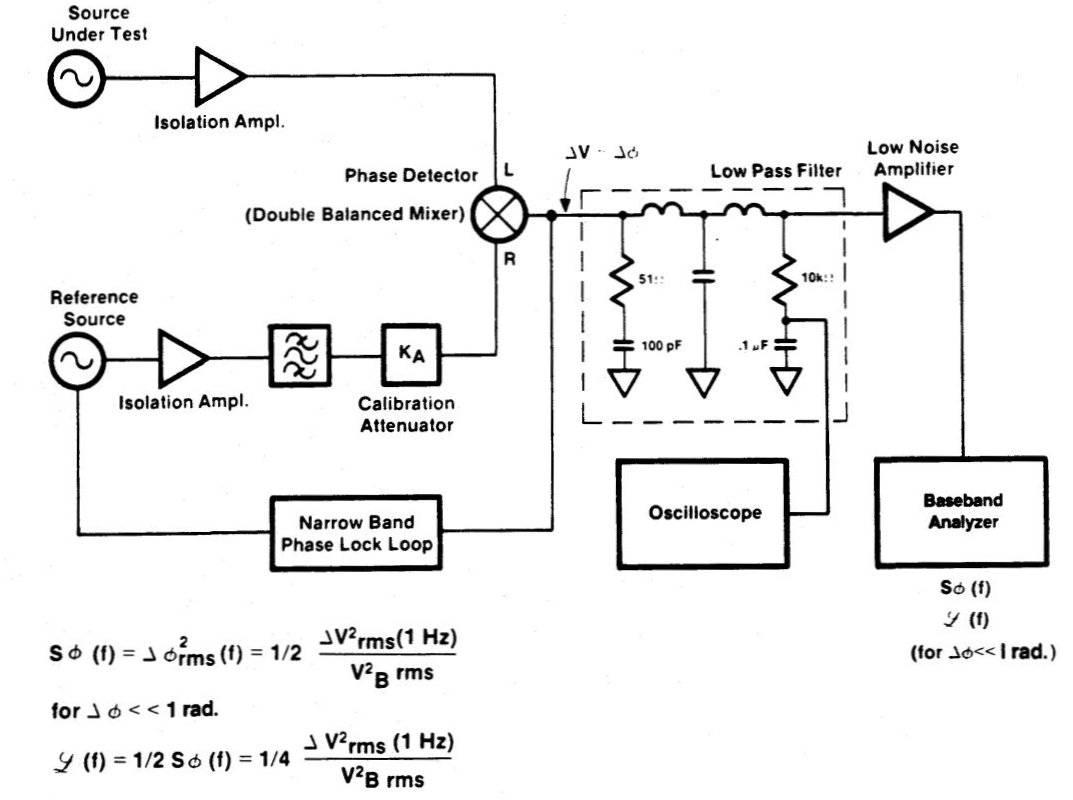
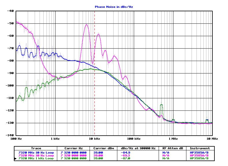
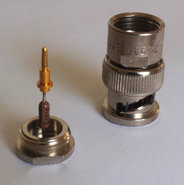
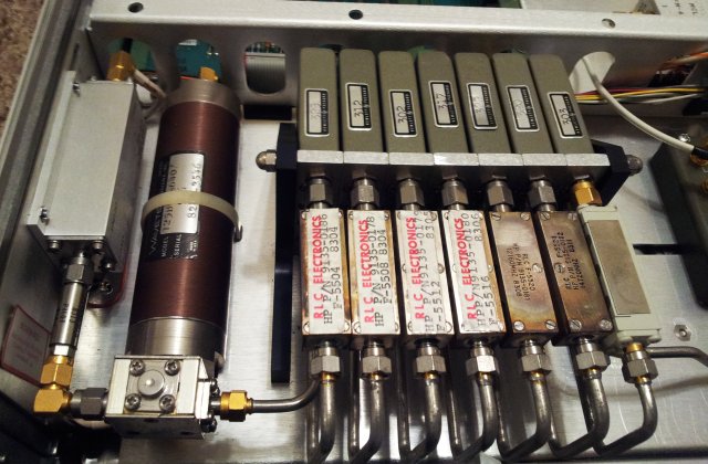
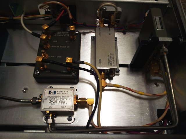
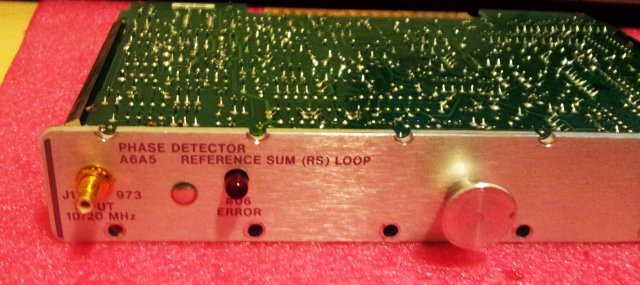
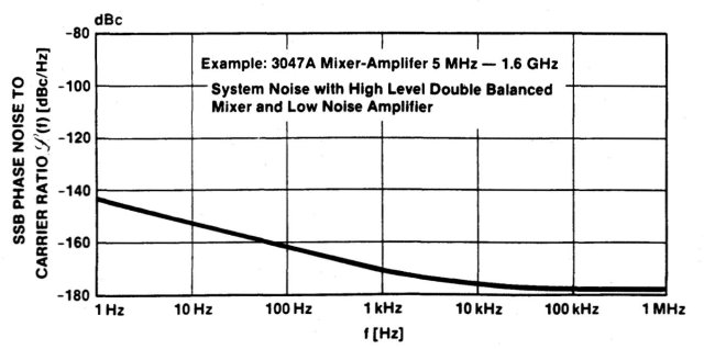
The noise floor, depends on the mixer (the 35601A has two mixers, one for the 5 MHz to 1.6 GHz range, and a second mixer for up to 18 GHz – the later one has about 10 dB reduced sensitivity).
3047a noise floor

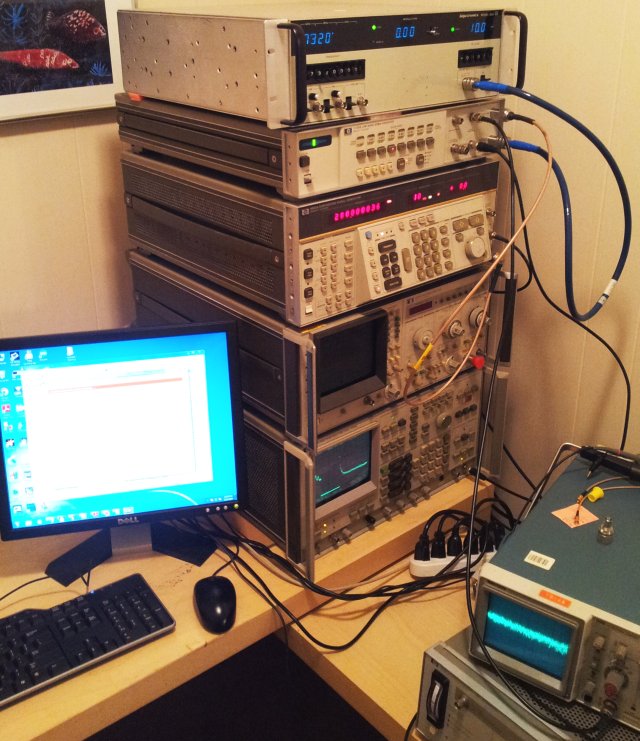
So far, the system is running with a 3585A analyzer only, with temporary software, at single frequencies. The 3047A employs the 3585A analyzer from 25 kHz onwards, and a 3582A FFT analyzer for the lower frequencies; this will be replaced by a 3562A. The 3585A is also used to measure the correction factors of the interface, which is rather straightforward because of the build-in tracking generator.

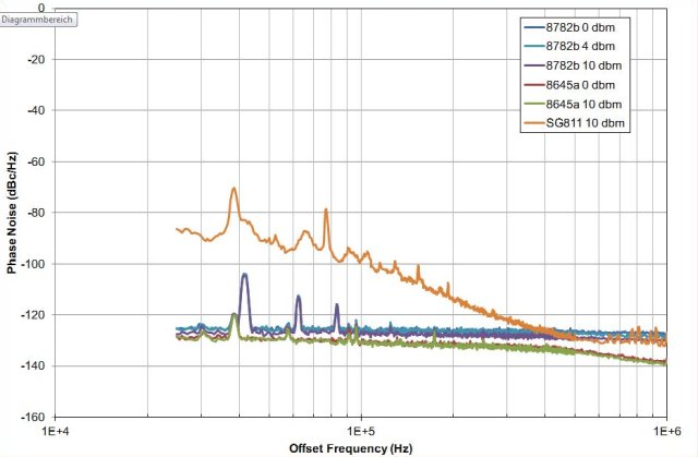
Now, after some more programming, some first measurements, of a few generators I have around here (8645A, 8782B, and a Micro-Tel SG811). As a reference the 8662A is used, so the 8645A can’t perform to its full specs – the measurement is limited by the reference.

3047a 3585a analyzer test

Next steps: improving the 3562A functionality, for lower frequencies – this requires some more work on the HP code, which was written for a 3582A analyzer. And, finally, making it a bit more easy and intuitive to use.

Controlling the 35601A Spectrum Analyzer Interface

Amongst other heavy boxes, the HPAK (HP Agilent now Keysight) 35601A is one of the instruments that form the venerable 3047A phase noise measurement system.
It contains two phase detectors (for up to 1.6 GHz, and for up to 18 GHz), a 40 db low noise amplifier, and other useful components to form a PLL (lead lag network, lock detector, a DAC, and a PLL to drive a low frequency signal from the 3585A IF).

35601a block diagram

This is the block diagram, sorry for the bad quality, it is the best I have, and you can read it with a magnifying glass. The 35601A has all kinds of switches that are GPIB controlled. The original HP software requires a particular dialect of BASIC, no longer used these days.

Therefore, the little program below might be helpful, written in C (compiles with GCC, and most other C compilers). Sorry, not particularly user friendly or anything, but those having ordinary skill in the art will know how to use it. The binary is quite useful for a quick check of the 35601A. Just connect a 10 MHz reference, and a 10 MHz VCO with about 10 kHz per V tuning range (like a 8662A with DC FM), and you can watch to PLL close.

PLL unlocked (see the upper yellow LED illuminated, indicating an open phase lock loop):
35601a not locked

PLL locked (the upper LED is dark!):
35601a locked

The program files. Working with a National Instruments GPIB interface card, but can be adapted to other cards with little effort.
sw35601 program 150227

Please, no unfavorable comments about the Tektronix 2215. It is still a very good scope, despite the obvious lack of a LCD screen and gigabytes worth of sample memory (it doesn’t have any memory).

11729B Test Set: quick phase noise check of a Giga-Tronics 605

Some experimentation with the recently acquired 11729B test set: measuring the noise floor of a Giga-Tronics 605 synthesizer, running at about 7.2 GHz.

To do this, more than 250 pounds of equipment stacked up:
mw pn test setup

On top, the Giga-Tronics, in the middle, the 11729B, and below, the 8662A (providing the low noise 640 MHz carrier for the multiplier of the 11729B, and the variable LO to adjust the IF to the analyzer range).
mw pn test set 2

Trying out two loop bandwidth on the 11729B, 10 Hz and 1 kHz. You can clearly see the loop impact on the measured noise:

11729b test

Blue curve – 10 Hz BW setting
Green curve – 1 kHz BW setting

All spectra were recorded using a 3585A, and the KE5FX PN software (which is really great for all general phase noise measurement tasks).

The purple curve – this is when the FM modulation is switched on, at 0 amplitude – still, it introduces quite a bit of noise!

BNC 50 Ohm Termination: a rather surprising construction

Doing some precise level measurement on 50 Ohm system, I came across this termination, Model 24931 28P296-1.

termination 1

It’s resistance, not quite 50 Ohms, but 51.1 Ohm… not that the DC resistance is the most important characteristics of a 50 Ohm termination, but nevertheless, a reason to check it.

This termination is constructed using a BNC connector, so I expected some kind of thin film resistor inside, maybe damaged by overload or age, leading to the incorrect resistance.

Opening it up, this it what I found:

termination rn55d 51r1 resistor

termination

The resistive element, a Vishay Dale R55D metal film resistor:
vishay rn55 resistor

And, in fact, it is a 51.1 Ohm, +-100 ppm/K tempco resistor. 0.1 Watts so it is running close to its limit already at 20 dBm! Don’t have the right tools here to measure ‘low frequency’ (< 2 GHz) SWR... but will check back home at the main workshop one time in the future, just for curiosity.

11729B Low Noise Down Converter: a small box, with very low noise

In an effort to upgrade my phase noise measurement system, look what I found, for less than 1 cent, for the earlier list price in dollars: a quite amazing HP (Agilent, now: Keysight) 11729B, equipped with all bands from 0 to 18 GHz.

The 11729B works best with a 8662A generator, to supply a 640 MHz low noise signal, and a variable 0-1280 MHz to move the IF to the right position.

11729b front

11729b inner workings

11729b scheme

The 640 MHz low noise signal from the 8662A is filtered by a quite massive Wavetek filter, amplified to about 30 dBm (1 Watt), driving a HP 33004A-H18 comb generator. The right line is selected by a filter assembly, using multiple 18 GHz coax relais. HP did not save on parts here….

11729b comb gen and filter

11729b mixer and if amp

The “brain”, a MC68B09P, a trusty 8 bit CPU, or as Motorola calls it, a “Microprocessing Unit”.

11729-60008 cpu ram rom

Just in case you need it, the ROM file, stored on a 2764 EPROM. Version 2.1!

11729b v2.1

8662A Synthesized Signal Generator: another rather straightforward repair

These 8662A generators keep coming in, seems that after so many years (like, 30 years) of 24/7 service, some little things are coming up. But not really sure if the frequency of failure/repair really increases, because with all these 1000s of parts, most of the units have seen some repair already, and it is just in the ordinary course of things that there can be defects every once in a while.

This unit add issues with the reference sum loop (A6A5), showing up in intervals of about 10-20 MHz. Knowing that a 10/20 MHz reference is used for the ref sum loop assy, this was the first and most likely cause of the defect. So, I substituted the 10/20 MHz signal, but, to no effect. Therefore, the defect is most likely located on the A6A5 assy.

8662a a6a5

One option would be to switch the assembly with one of my 8662A/8663A units, but these are currently in use and I don’t want to pull out assemblies that are difficult to fix and need adjustments, etc.

So, next, checked the pre-tune circuit, and, issue found. TP14 is at a constant -2 V, rather than variable voltage as per requirement given in the service manual. Digital input is OK – maybe the fault is in the semiconductors – one transistor, and 4 FETs switching a current source.
With spares at hand, these suspicious parts were quickly replaced. Effect: no effect. Big mystery.

Now, connected an external resistor, to measure the pretune DAC (4 FETs), and, it works! Even more mysterious.

Finally, also checked the traces and the resistors, and found the ‘2K’ Trimpot to have about 40k!! With the wiper contact having some effect, but not much.

8662a a6a5 assy schematic

8662 defective trimpot

Desoldering the Trimpot – all seems to be OK with it. Maybe some kind of aged solder joint? Whatever it was, the Trimpot is now fixed, the A6A5 assy re-adjusted, and the 8662A working again!!

Wheat Corn Bread – an easy recipe

Breads are mostly made from wheat and rye flour. This is at least a common misconception of the westerner, living in the Northern hemisphere. Almost all kinds of grain can be used to prepare bread, albeit, bread of different shape, depending on structure of the flour, and the rising agent used.

Here, a simple recipe that uses a combination of wheat and corn flour, with yeast as the rising agent.

corn flour

In a big bowl, mix:

1000 g of unbleached wheat flour
600 g of corn flour (masa type, nixtamalized)
30 g of salt (measure rather accurately)
1 bag of active dry yeast

To the mixed powders:
80 g sunflower oil, or pumpkin seed oil
1450 g of water

Corn flour absorbs a fair bit of water, you might need to add up to ~150 g more, depending on the type.

Mix properly, best done using hands rather than a big machine.

Let rise for about 1.5 hours, until you see a considerably increased size.

Portion into about 16 to 20 parts, twist them a bit and put on non-stick paper, on a baking tray.

ready for oven

Bake at about 400-450 F, 200-230 C, for about 22-25 minutes. Oven needs to be properly pre-heated. If at all possible, add 1-2 cups of water on a lower tray, to generate steam during the first part of the baking time.

fresh bread

Mmmmhhh! Very delicious!

One variation – mix 1/2 package of yeast, 500 g of the wheat flour, and 500 g of water – the day before the baking, and let sit overnight, at moderately warm temperature (about 70 F, 20 C). For baking, just add the remaining quantities of the ingredients as per the list above. This will give more coarse pores, and adds a particular refined taste.