Another Micro-Tel 1295 Precision Attenuation Measurement Receiver: irresistible green

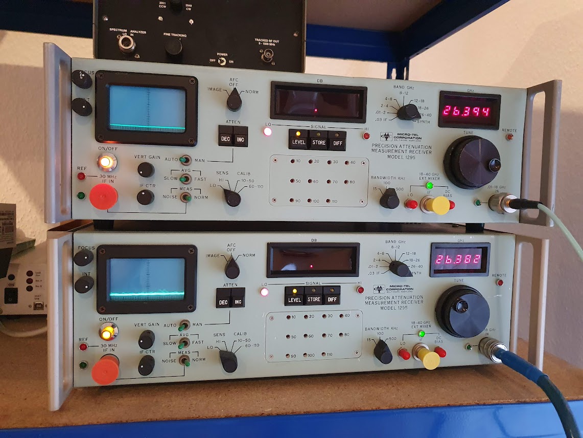
I am trying hard to resist the temptation of buying more test equipment, but the Micro-tel special green color has a hypnotic effect on me, and combined with the right price, I could not resist to buy one more Micro-tel 1295 receiver. These are very capable 0.01~40 GHz fundamental-mixing receiver (fundamental mixer until 18 GHz, above that, harmonic mixer), with very large range, like, 120 dB, and 0.001 dB attenuation resolution. Ideally suited to calibrate attenuators or to check antennas, etc.

The unit – offered as non-working – arrived very well packed. Unfortunately, many people send sensitive equipment in some thin cardboard boxes. This particular equipment cost close to 85 kEUR in 1989, plus mixers. Also, it has long been under export control from the US, because of its unique range and accuracy.

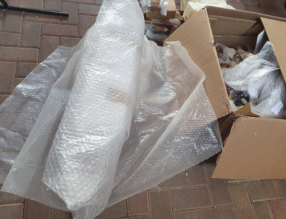
Bubble wrap, other fibre wrap inside.

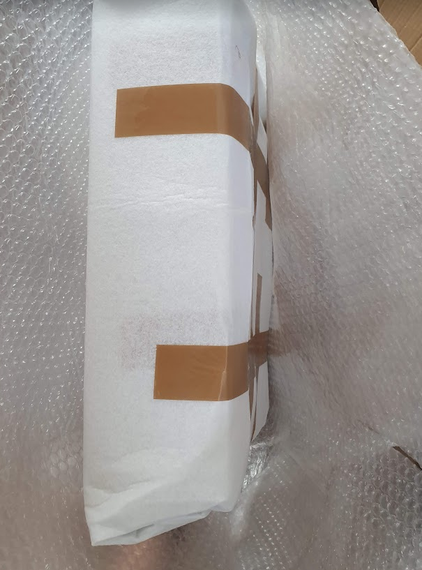
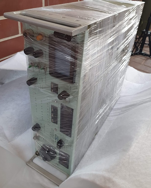
Finally all in foil.

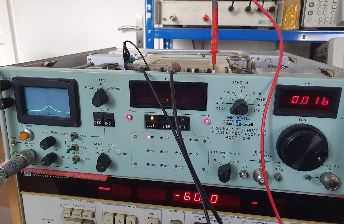
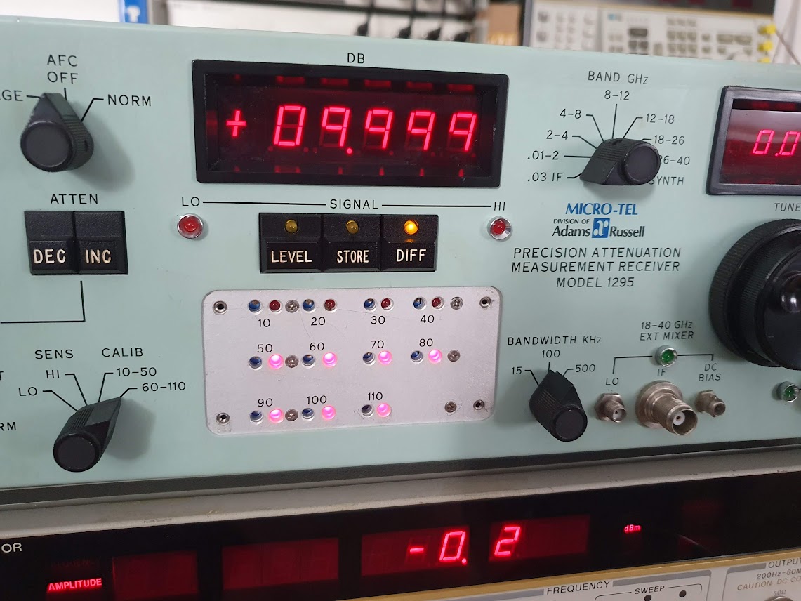
The defect, it doesn’t show any reading on the display, and both the HI and LO leds are on, which is abnormal. The 1295 has a 12 dB range bolometer detector, any signal below 0.5 dB or above 12.5 dB will light up the LO or HI lamp, and you would need to select another 10 dB step of the IF attenuator (a high precision 30 MHz attenuator), or let the automatic attenuation selector do the job.

There are many boards inside, but all nicely numbered and with instructions in the manual.

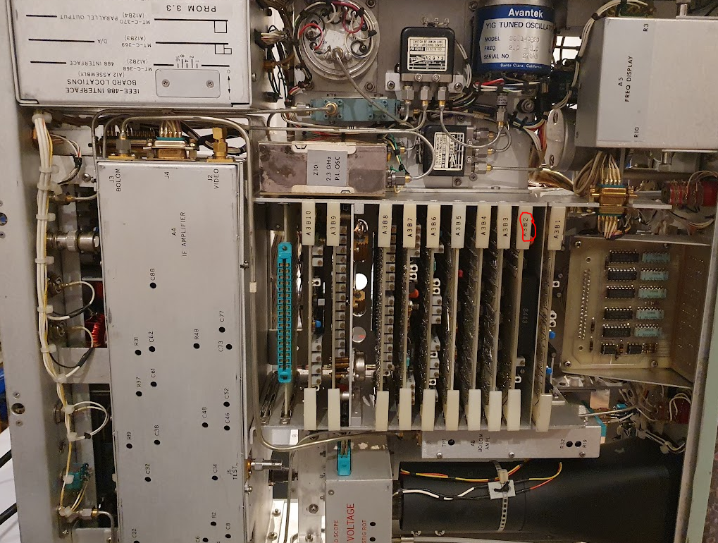
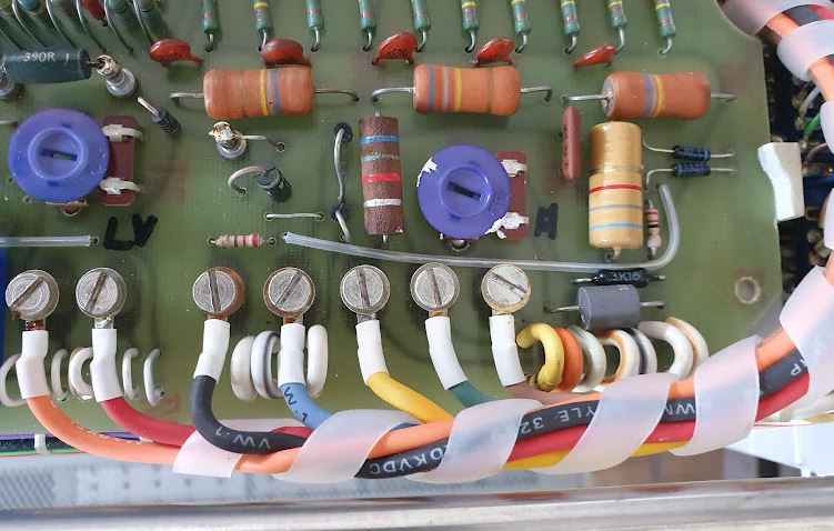
The HI and LO level detection is done on the A3B2 assy.

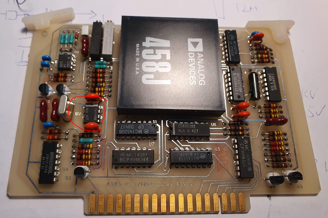
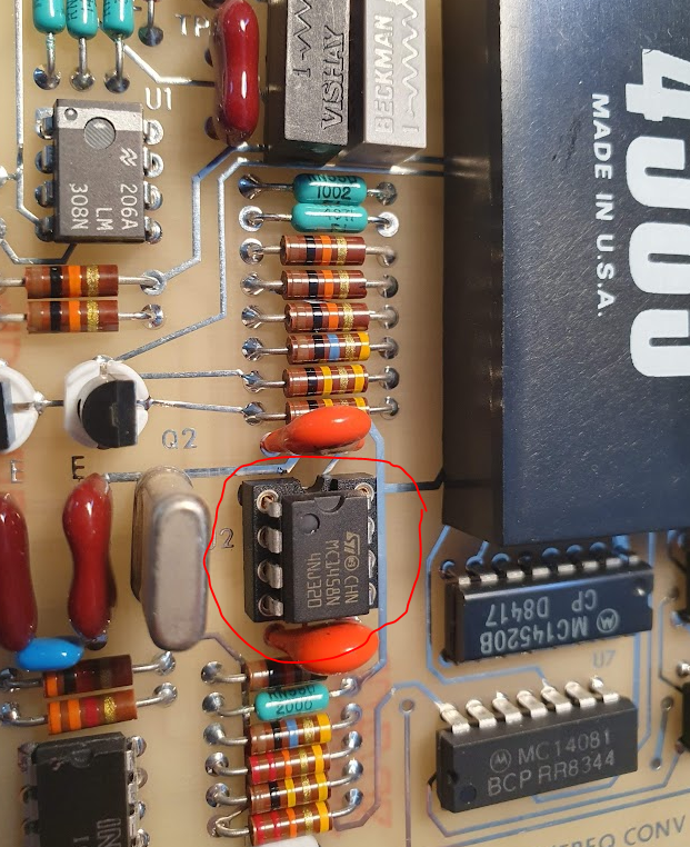
According the the schematic, U2, a MC1458 generic dual opamp is switching the LEDs and providing signals to drive the automatic attenuation selector.

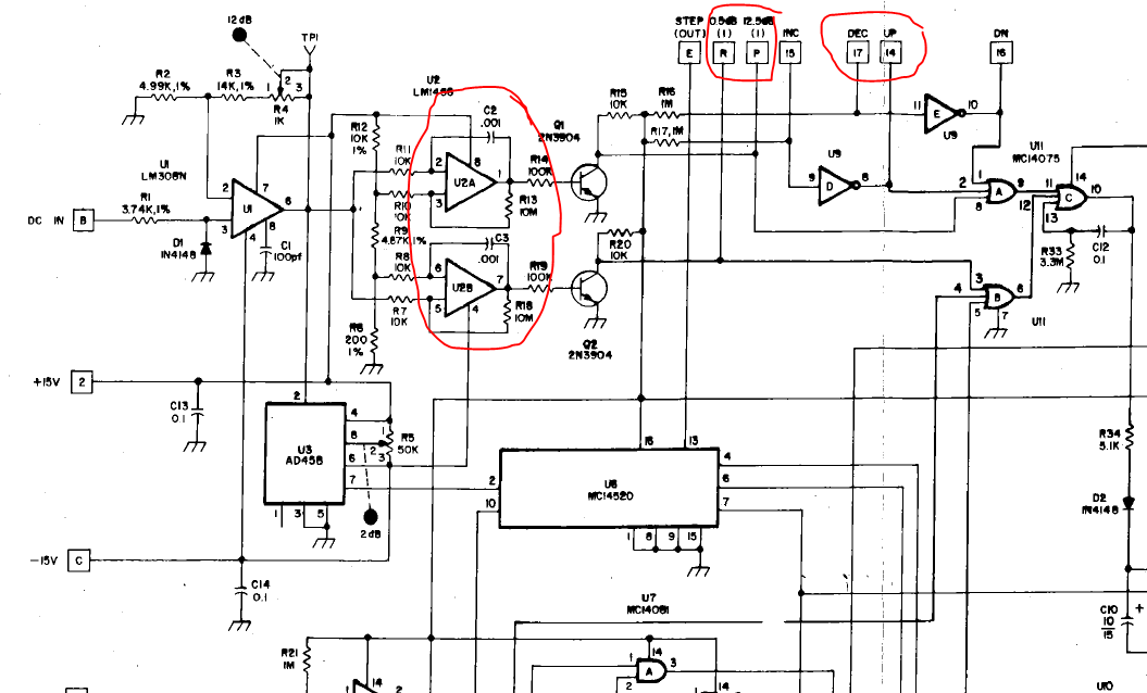
A quick check revealed that U2 is defective, so I replaced it quickly, and this already solved the issue and brought back the display.

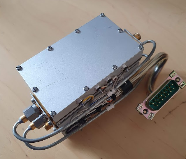
Another trouble related to unstable lock of the 2.3 GHZ auxiliary LO that is used for the 0.01-2 GHz range (which uses a two-stage down mixing).

Fortunately, I had a spare 2.3 GHz from my parts unit (which I bought years ago – a partial unit – while I was living in the US). That part was missing one of its covers, and had also some issues earlier, but I had fixed it a while back just for curiosity. Now I can fix the unstable 2.3 GHz removed from the unit during next winter. It has a 2.3 GHz VCO, a 100 MHz local oscillator and a PLL inside.

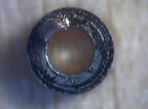
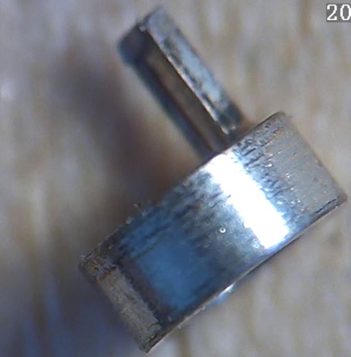
After calibrating all the oscillator frequencies, which went without trouble, I noticed that the top 120 dB attenuator was 0.04 dB off, well, not a big deviation, but I would rather have the unit working perfectly. So I removed the attenuator for further study.

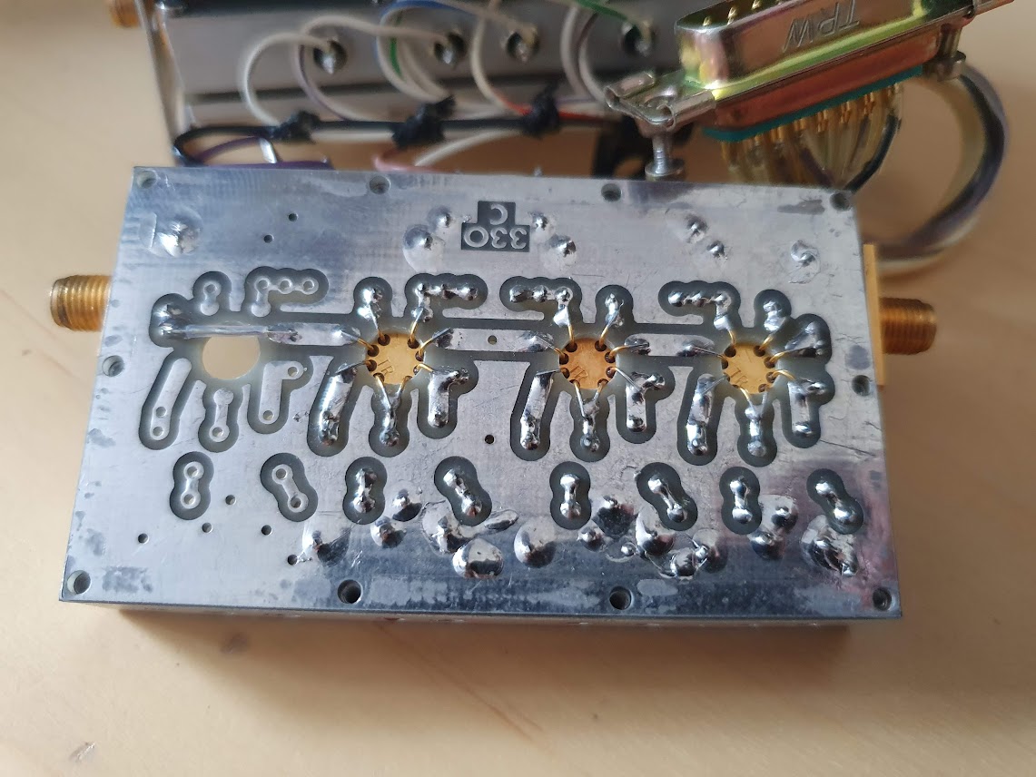
It is build with really high quality relais, more than USD 50 (each!!), and some precision resistors.

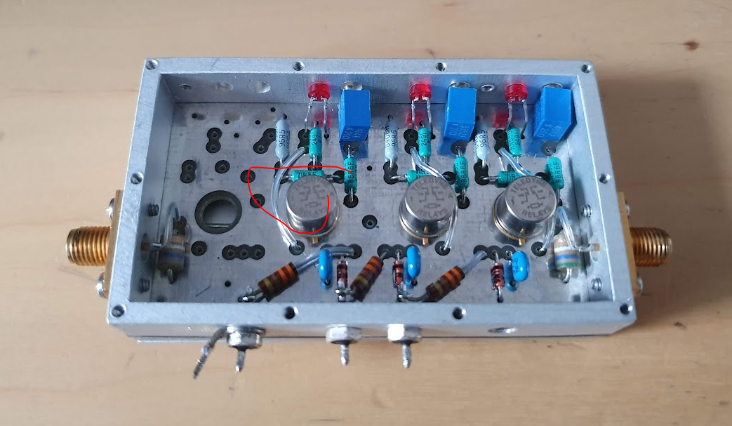
Nothing could be found wrong with the unit by visual inspection.

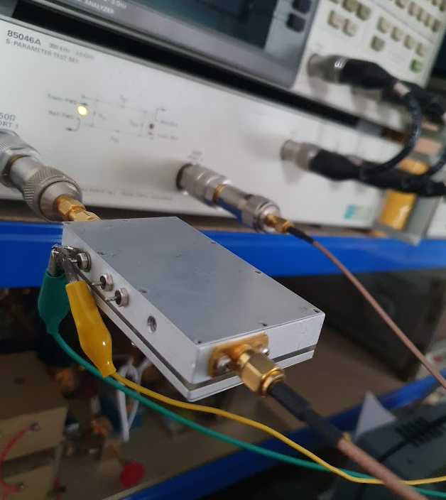
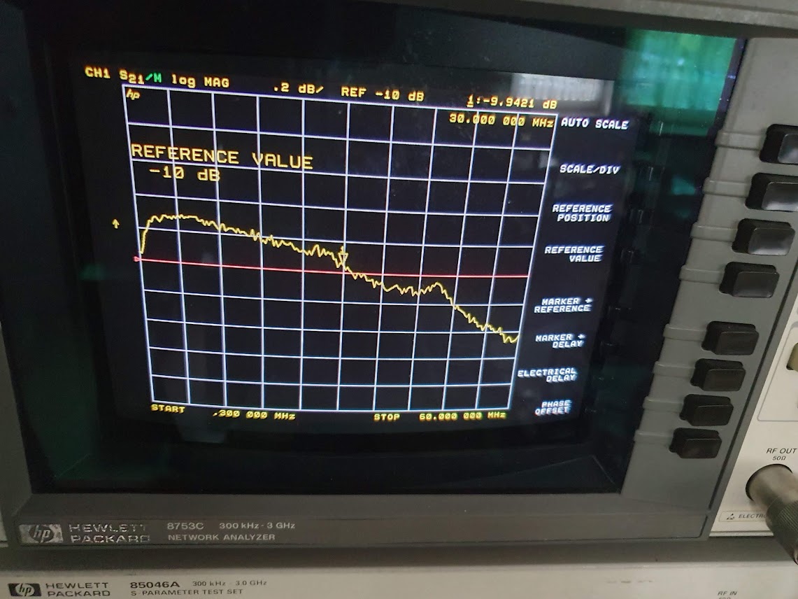
Also I used the VNA to check the attenuator, and all seems well working.

All the 3 segments, virtually equal at 10 dB each.

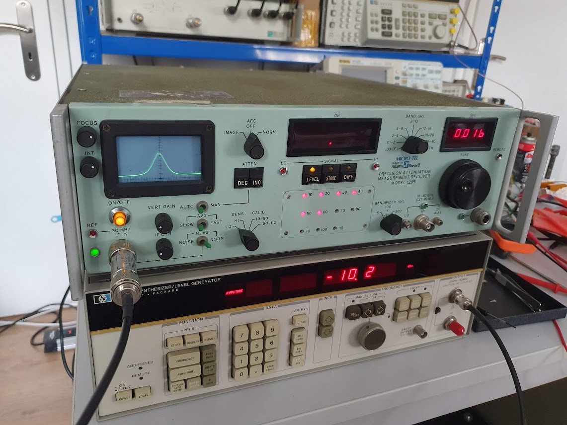
Finally, I put everything back together, a little clueless, but, now, for some reason, all is working and stable. Maybe it was some lose connector, or other strange effect that is now gone. All attenuators calibrated perfectly, using by HP 3335A level generator (which has a top-accuracy attenuator).

Finally the 1295, working just perfectly fine. Maybe better than ever before.

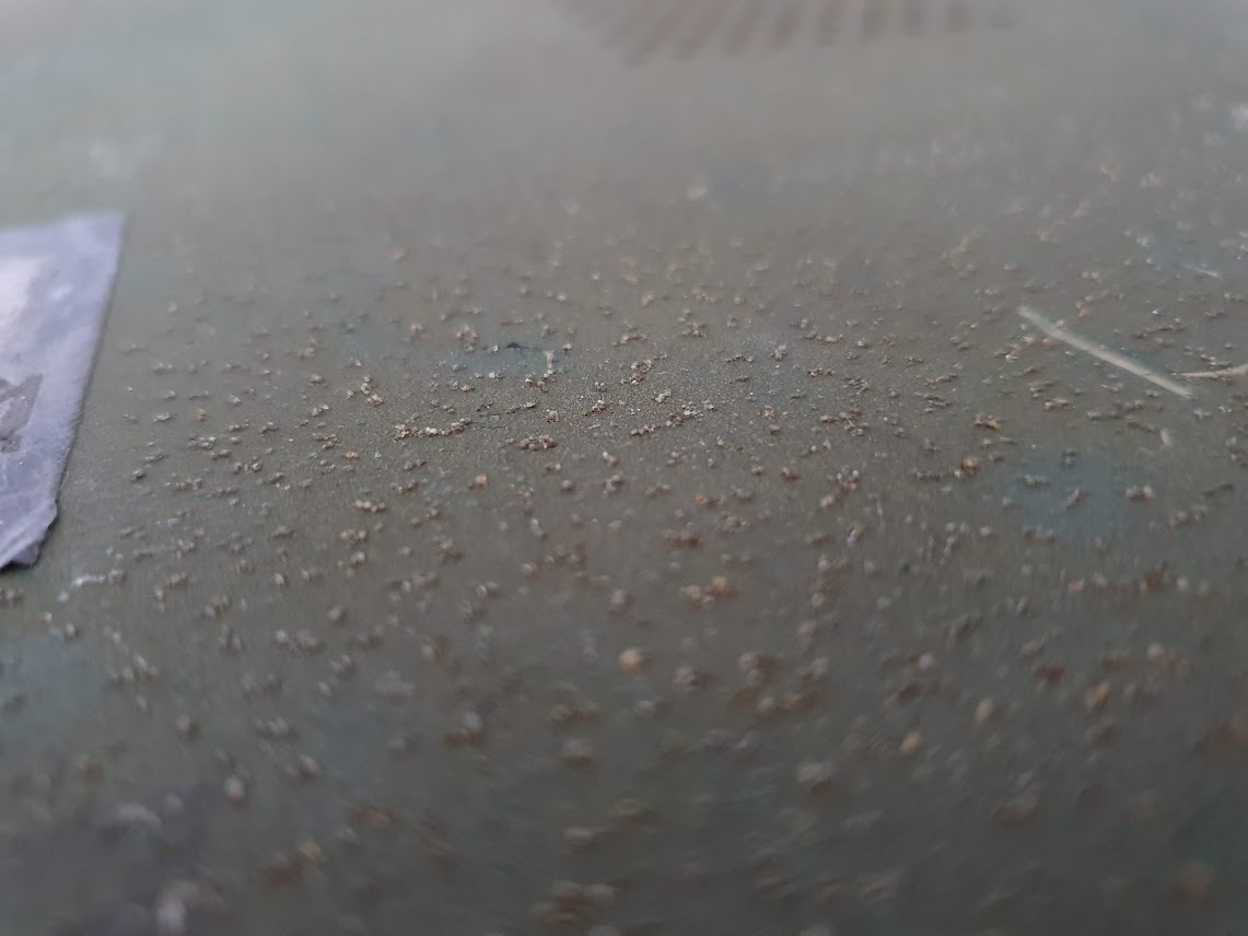
Interestingly, as with all of these Micro-tel devices, the side and top/bottom panels were painted with various kinds of special military paint – some with a rubberized paint that will dissolve into some gluey substance over time, some with a type of “abrasive” paint, other already re-painted in forest green.

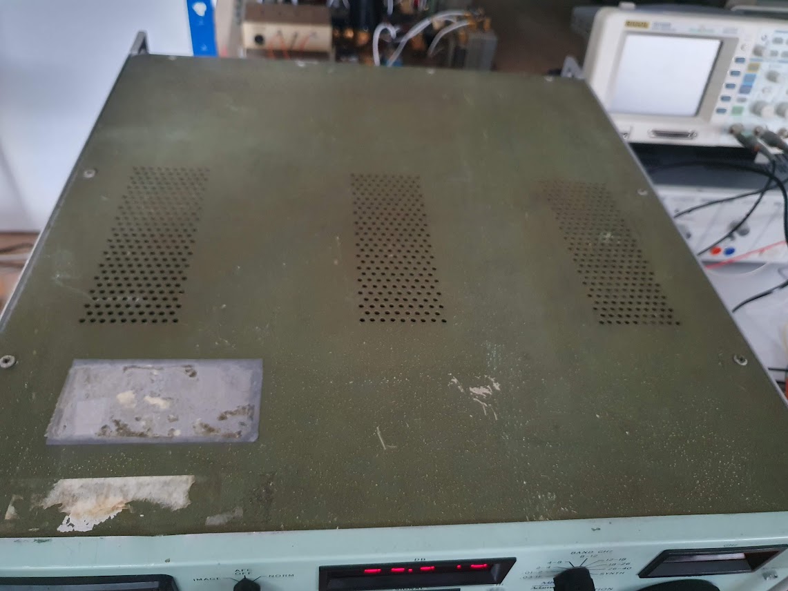
The paint has very large and hard grit, almost like sandpaper. But I will leave it untouched, it seems the original looks for this serial number range (the 1295 seems to have been in production for 10+ years).

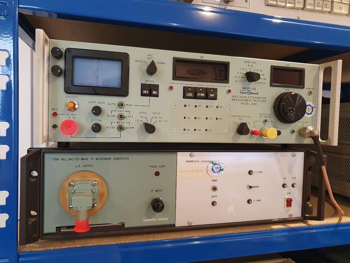
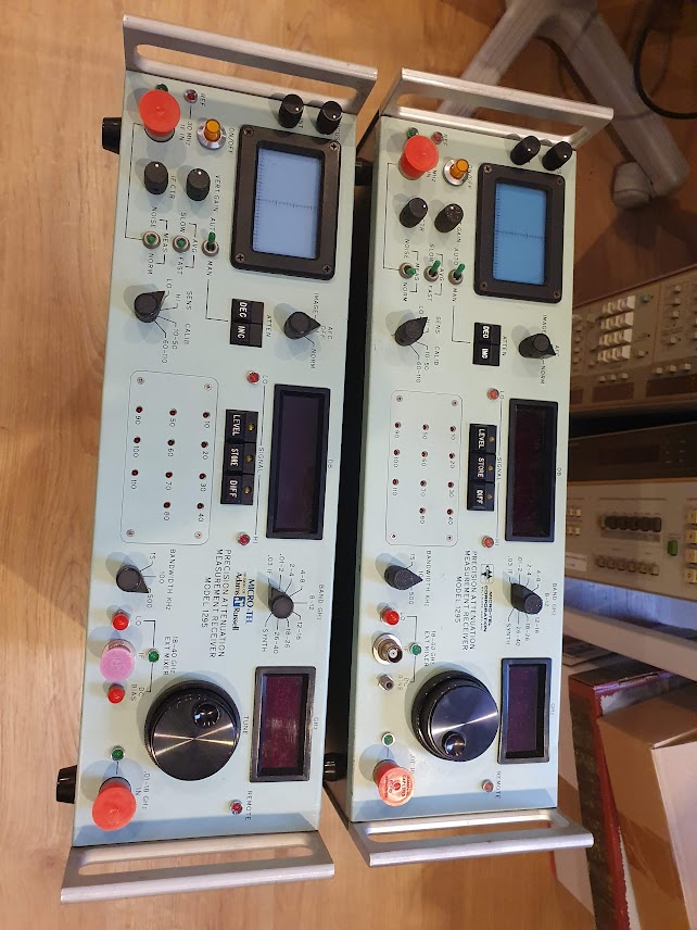
Now, a little gallery of all my Micro-tel 1295 receivers: the first two, part of my frequency-locked attenuator calibrator (can measure reflection and transmission at the same time).

One as part of an E-band (60-90 GHz down-converter).

Any now, already two spare units in perfect calibration.

Still, in the basement, a box of spares… likely I won’t run short of receivers soon. Maybe even buy another one should it come around.

Watkins-Johnson SE222-50 Backward Wave Oscillator: the magic helix

Recently, I got a Marconi Instruments Model 6651 RF Plug-in (26.5-40 GHz), for the 6600 sweep generator. These were basically the 1st generation sweep generators extending into the millimeter wave region.

A number of plug-ins were available, mostly based on Watkins-Johnson BWO (backward wave oscillators), which are a particular type of electron tube.

These sweepers were first introduced in the late 1960s, early 1970s. New plug-ins became available as development of BWOs and similar sources advanced.

I have no price list, but surely these items came at a hefty price tag in these early days, even not quite cheap today.

My unit had a pretty “new” 1990 date-code BWO, I expect, it had been replaced by its former university owner at least once, also the cables and connectors of the BWO looks newer compared to the rest of the plug-in. Because of their nature, the BWOs only have a limited life-time, a few 1000 hours at best.

There are numerous warning labels, because to focus the electron beam, a strong magnetic field is needed.

The output is a gold-plated waveguide flange, for Ku-band waveguides.

The general layout of a BWO: there is an electron gun, producing, in our case, a hollow electron beam, with the necessary heater, kathode, anode. Then, the helix, and the collector (which is basically at helix potential or a little bit higher, say, 100 volts higher. The helix voltage is quite high, for exmaple, 1~1.5 kV.

While there is no information from Watkins-Johnson available online for any of these devices, a lot can be learned from related Hewlett-Packard microwave sweeper plug-ins (8697A), where (arguable) the same or very similar BWO has been used (some HP units may use Varian BWOs).

Unfortunately, after quite some effort with high voltages and pretty dangerous tests, it became clear that the tube barely gave some power. Maybe, because it had not been operated for a long time (some people and datasheets say that the BWO should be run at last once every 6 months, or similar, to preserve its function…).

But anyway, I have other, more stable and easy to use sources for this range, so I didn’t want to scrap the BWO without having a closer look at this. When do you normally get a chance to check out the secret workings of such marvelous devices!

First things first, hidden inside a heavy magnet, silicon rubber, and a waveguide coupler: the tube. A very mysterious piece of engineering, only a few companies ever mastered to produce these.

Also by the numbers and hand-writing, pretty clear that these units were all hand-made and assembled by engineers and highly skilled people.

The mount is all gold plated, a tapered wave guide eventually bent by 90°, so the microwave radian can be coupled from a small gap in the silver coating of the tube, to the outlet. This tube was meant to generate about 10 dBm.

The helix at the collector end.

You can see, the helix is kept centered by 3 glass (quarz?) rods, these rods are just held in place by the tension of the helix, but normally won’t move during operation and shipment. Surely, will all the glass-metal interfaces, mounts and connection points, it is no good idea to drop these units – some interfaces may break, or mis-align beyond repair. Furthermore, several Watts of powder will need to be dissipated, calling for a reasonably elaborate design of the mount not only to conduct the microwave radiation from the tube to the output, but also to dissipate the heat from the collector and helix.

All the high voltage socket part is embedded in two layers of silicon rubber. First they put some denser rubber around the socket to fix everything in place, probably run some tests, and then sealed it all by filling the further space with some pretty soft, highly filled silicon rubber. What they didn’t consider – the cable also has silicon isolation, and deteriorates in contact with other silicon materials. This may be one of the reasons for the unstable operation, because some wires were pretty close and the isolation seems very brittle.

Furthermore, I did some measurements of the critical parts, just in case I would even want to fabricate own BWOs, at least I have some working dimensions to start with.

The helix is normally made from flat molybdenum strip. At the bottom (gun end) it is mounted to a small ring. Scale is 210 px per 1 mm, in case you want to take dimensions…

A typical power supply – I am thinking about building a BWO power supply for some other old BWOs I have around (for other frequency regions), but it is fairly involved – the old design used high voltage 2 kV transformer with further high-voltage stable windings to provide the collector offset voltage, several expensive high voltage capacitors, and high voltage regulation vacuum tubes. I think it will be a good challenge for winter to build a 2 kV regulated and low-ripple power supply, solid state, probably with some series-connected MOSFETs.

Any of such future supplies will need a pretty special plug: heater voltage, anode and cathode voltages, helix voltage, collector voltage. At least I can go without any analog linearization voltage, if I manage to make the helix supply digitally controllable.

Inside the 6651 plug-in the BWO is connected to the board with some screw terminals. Seems to work well even at the high voltages. Surely there is no touch protection for these devices, just a few warnings not to get too close!