Micro-Tel MSR-902C Microwave Surveillance Receiver: A3B5 and A3B6 analysis and repair

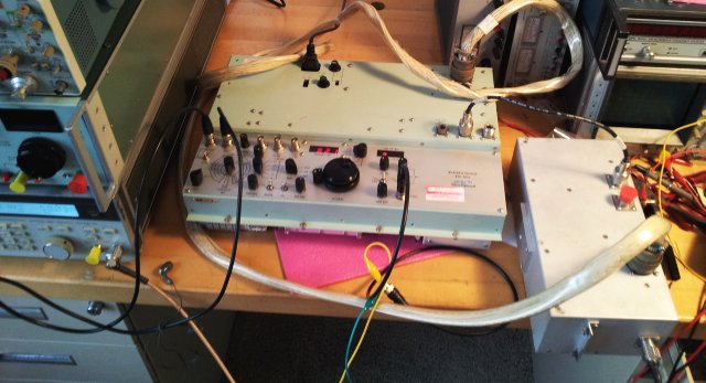
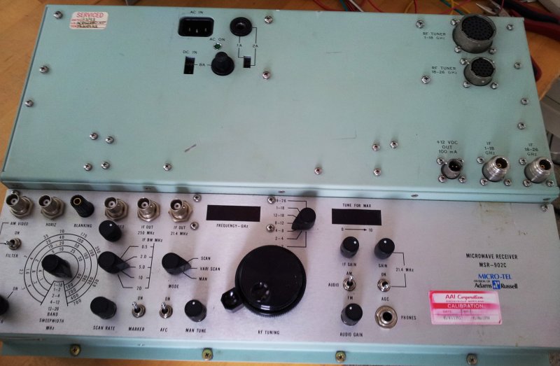
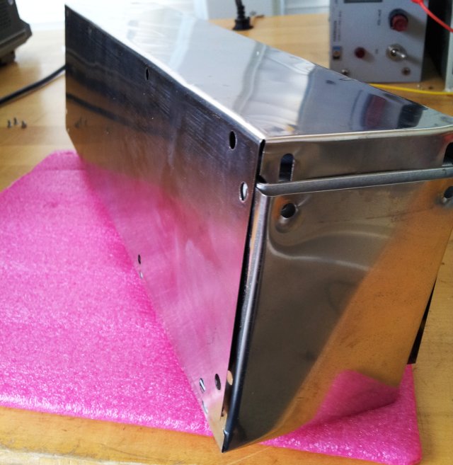
Some progress with the MSR-902C, which is basically working, but not on all bands – see earlier post.
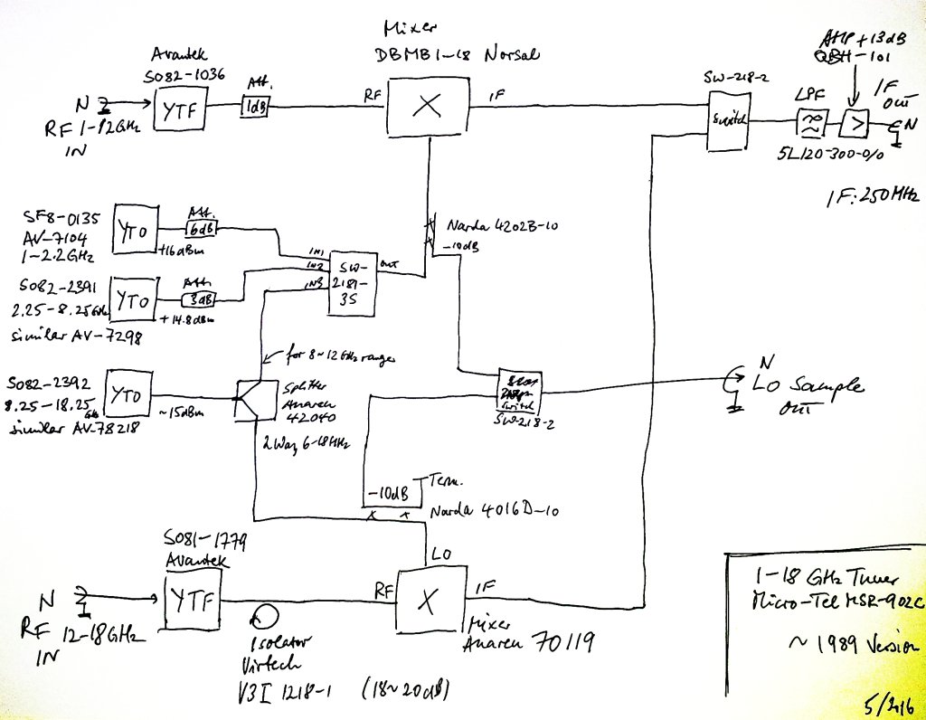
With no documentation on the MSR-902C available, except some data sheets, I first traced the band select signals – and they appear to be generated on the A3B5 board, which we may call, band control board. This board also converts the 0-4 V tuning voltage from the tune dial to a 0.5-9 V signal that corresponds to 1 to 18 GHz (0.5 V/GHz slope).

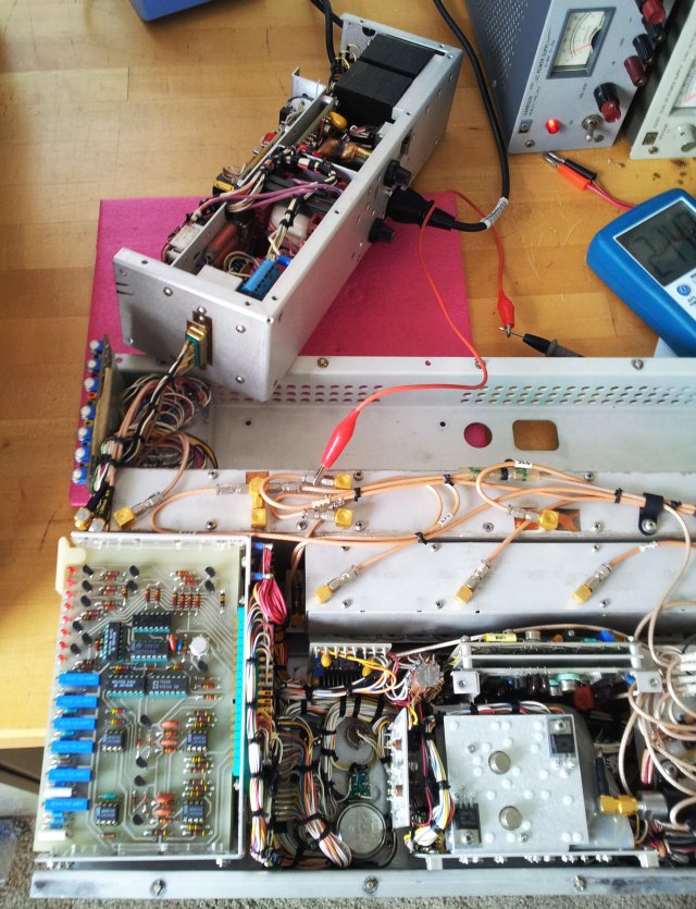
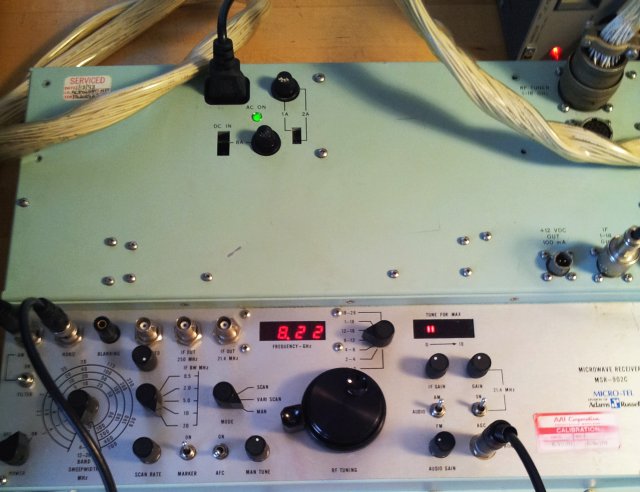
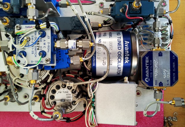
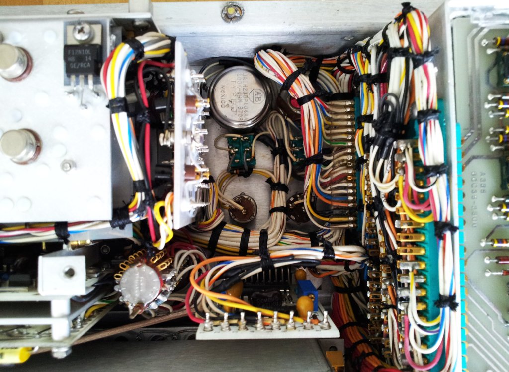
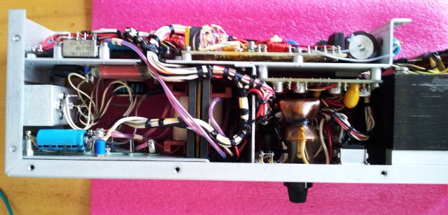
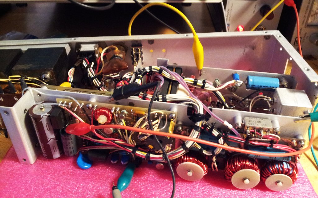
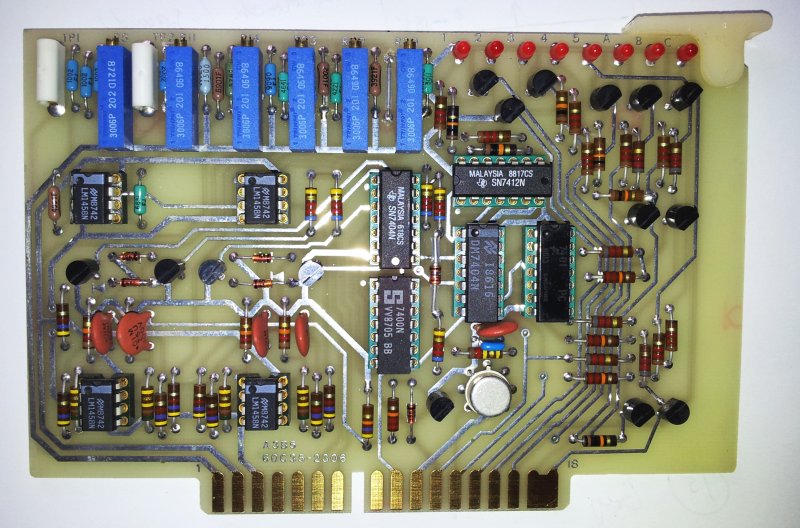
This is a top view of the A3B5 assembly. On the upper left, the tuning control voltage converter, left half, voltage comparators for the 1-18 GHz multi-band mode. These comparators assign the band number to the tuning voltage, when the 1-18 GHz range is used. It is disabled (even supply voltage cut) when the MSR-902C is in single-band mode (selected by band selector switch).

msr-902c a3b5 assy 60c35-2306

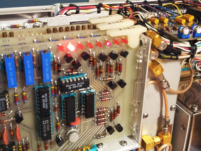
First observations – there are control LEDs that seem to indicate which band is currently active, but for some reason, they don’t light up on all bands. Very strange. Probed around the logic signals, and at least some signals are there, still no LED lighting up. Very suspicious. After some head-scratching, decided to probe the LEDs by supplying some external power, and poking around with a resistor. Turns out, some of the LEDs are dead. They just barely light up with 20 mA of current applied, and no sign of light at all at the current level supplied to them by the A3B5 assy.

msr-902c a3b5 led test

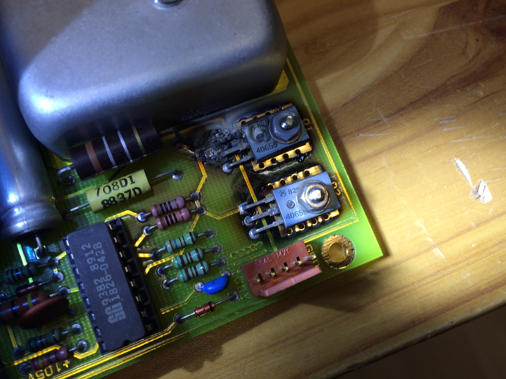
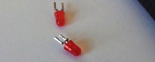
After repair of the defective leads, you can clearly see the difference of the new LED, vs. the old LED – some of the old ones are still working, but not very bright any more, and I’m going to replace them all, once I have this back in the main workshop with a better supply of 3 mm red LEDs.

msr-902c a3b5 led repair

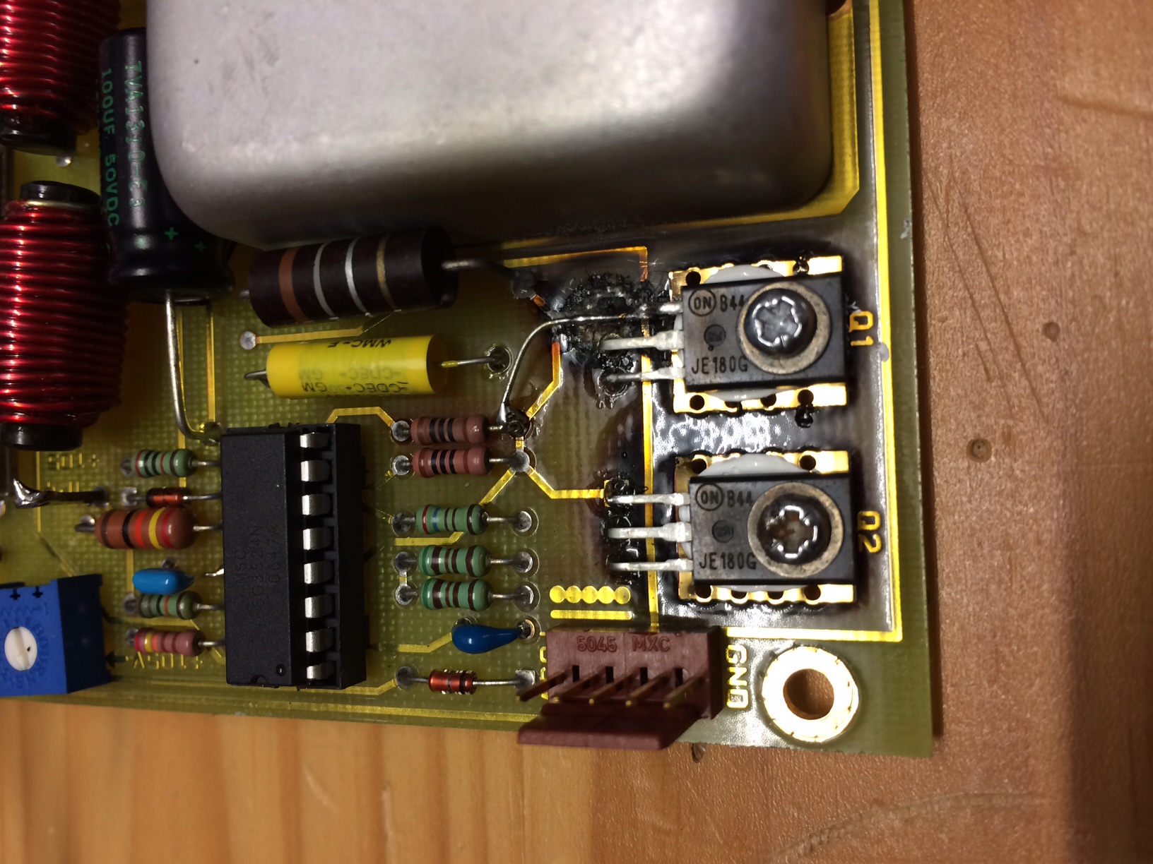
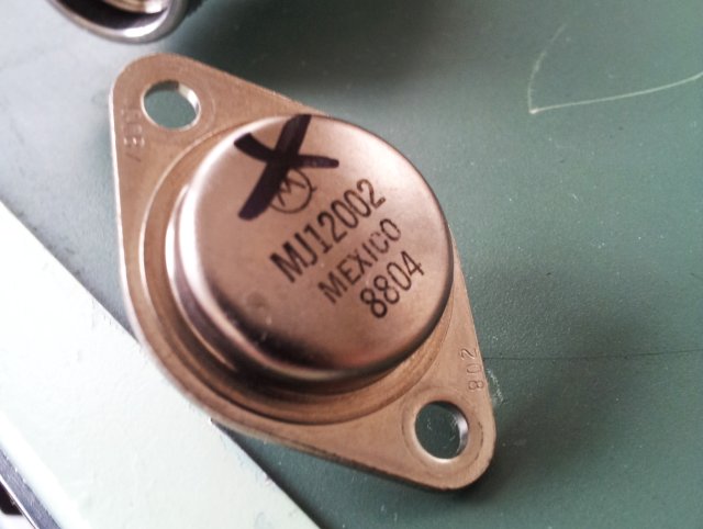
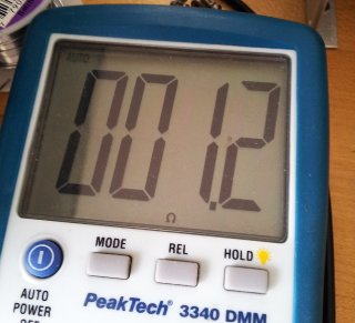
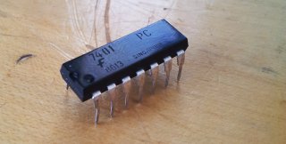
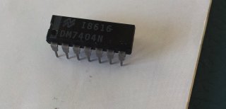
Another strange observation – two of the logic chips are rather hot. What is going on there? Furtunately, these are in sockets, a 7401, and a 7404, and a quick test revealed that one gate of each of these chips is sinking current, about 200 mA. So these need to be replaced.

Mugshots of the culprits so far….

msr-902c a3b5 dead leds

msr-902c a3b5 dead 7401

msr-902c a3b5 dead 7404

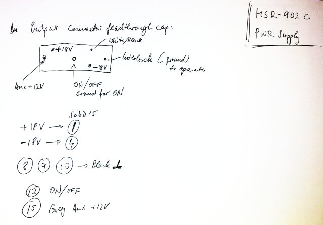
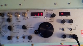
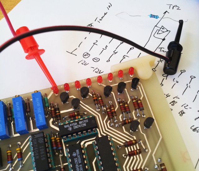
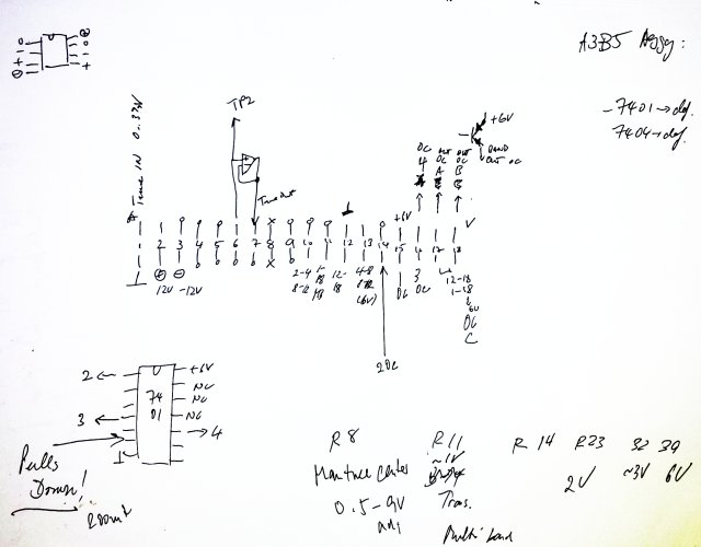
Not sure if it is very clear, but here are the connector signals of the A3B5 assy, and the description of the adjustment pots. First adjust for appropriate tuning voltages, then adjust for proper band switching in multi-band mode, monitoring the LEDs.

msr-902c a3b5 connector signals

msr-902c a3b5 adjustments

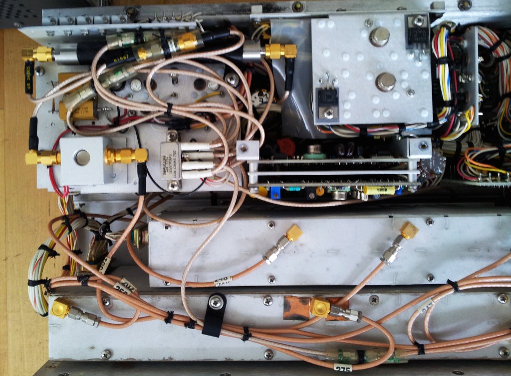
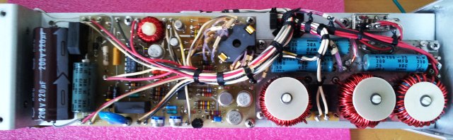
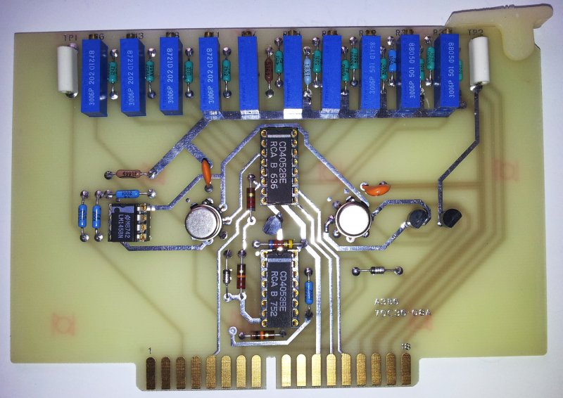
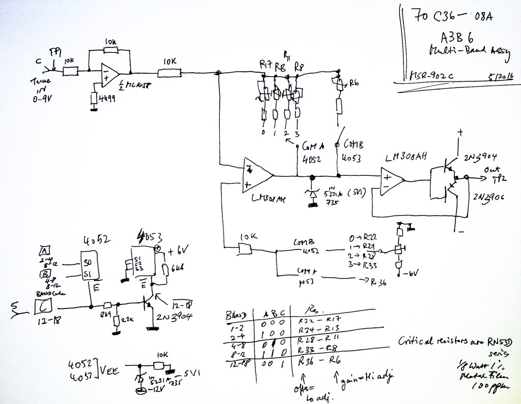
The next thing, the A3B6 assy. No apparent defect, but still needed to find out what it does, and how to adjust. It appears to be the multi-band control assy, converting the 1-18 GHz full-range tuning voltages to tuning voltages for the individual bands, by applying offset and slope corrections. The offsets/slopes are selected by CMOS multiplexers as it is custom for most of the MSR series designs. The output tuning voltage is buffered, and forwarded to the other circuits.

msr-902c a3b6 70c36-08a assy

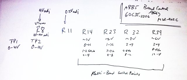
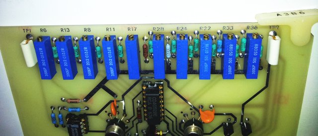
Here, you can clearly see the order of the adjustment potentiometers. For adjustment, if may be best to first align A3B5, and then supply appropriate reference signals to the MSR-902C, or measure the LO frequency, and do the fine adjustment with the 1-18 GHz full range mode selected, and tuning through all the bands. The fine adjustments would need to be done both at the low end (for offset), and at the high end (for gain), for each band. No big deal, once you know which of the pots to turn.

msr-902c a3b6 assy1

msr-902c a3b6 schematic and adjustments

Further repair will have to wait a bit, until a few spare 7401 have been received. But all is looking pretty good.

HP 8662A 8663A Power Supply A7A3 Assy: base transformer defect

A little note, Thanks to a kind fellow sharing this repair info with me, related to the A7A3 assy of the 8662/8663A generators: the 9100-4018 base drive transformer. There are two of these on the 08862-60289 board, protected by a fuse and diodes, nothing should acutally happen to them, but things can go wrong.

Below, the two versions of the A7A3 boards, left, the older 08662-60289, and the more recent 08662-60604. This post only refers to the -60289, the base drive transformers of the newer units look the same, but have part number 9100-5291 – don’t know if the can be exchanged.

8662 8663 pwr supply

A snipet of the power supply circuit, there are two identical base drive transformers, center tapped on one side.

08662-60289 base drive schematic

Cross reference – this is a NSN part, the most prominent manufacturer seems to have been Fil-Mag, which use to be a Sprague company long ago.

9100-4018 master cross ref

5950-01-267-1279 aka 9100-4018 transformer

Note that these little beasts come at a quite hefty price! That’s well over USD 100, just for the two base drive transformers – I hope, HP did not pay the list price, or anywhere close to it.

Here is a rare view of the interals, after heavy work with sandpaper and other means (these transformers are potted, but as with all potting compounds it can be removed, if you have plenty of time, a good supply of tools and don’t mind the dust and dirt).

8662 8663 pwr fil-mag 42z994 internals

It uses an OJ41408 bobin/pot core, PC14/8 size. Wire is about 0.1 mm size. The pot cores are still available from Magnetics Corporation, mag-inc.com, and the material is just a regular mid-frequency ferrite. So you might be lucky with just using any average good pot core with about 5000 permittivity (e.g., N30 ferrite).

8662 8663 pwr oj41408

mag-inc 41408ug pot core

mag-inc j material

Fingers crossed that you will never need this information, because it is quite a laborious effort to reverse-engineer the internals, and to fabricate a new transformer manually. Tempted to say, I could manufactur them well below list price, if someone would need a 1000 pieces….

Micro-Tel MSR-902C Microwave Surveillance Receiver: power back on – first signs of (extraterrestrial?) life

Today, a few spare MJ12002 transistors arrived. No time to lose, and put them into the power supply. Note that the new transistors are 1983 data code, whereas the Micro-Tel originals were 1988… fixing the power supply with old parts, but no reason to assume that these transistors have any issues with age. With such power supplies, I would always suggest to use a pair of transistors of the same manufacturer, rather than mixing up two very different devices. This is why both transistors were replaced, not just the defective part.

msr-902c 8322 mj12002

After this replacement, connected a 10 Ohms 25 Watts load resistor, and grounded the Interlock and ON/OFF lines. When powering up, the green AC ON light comes on, but not for too long. Look at the set of fuses sacrificed in the process:

msr-902c pwr supply rep fuses

Another set of tests – no issues found, all working fine. Something must be loading the power supply, and I can’t get any negative voltages out of it – but there must be at least one negative rail to provide -15 V to the various opamps in the receiver.

Not to long and the culprit was found – a shorted tantalum, a T310 series Kemet tantalum, directly at the – what turned out to be, -18 V output. Check out the date code. Why did Micro-Tel put a 1979, week 38 dated device, in such kind of expensive and specialized equipment (other parts suggest that this unit was made about 1989, at a price of about $40-50k – that’s about $70k in today’s dollars…).

msr-902c tantalum

Some tests show that there is a +18 V, -18 V, and a +12 V output. All are routed through feed-through capacitors. A fair bit of effort, and cost!

msr-902c pwr supply output

First test with the actual receiver connected –

msr-902c first pwr test

– connected the 1-18 GHz tuner – a bit of a cable mess.

msr-902c test setup

To test the basic functions, like, IF chain, detectors, etc, a 1.5 GHz test signal from a HP 8642B was routed to the tuner. And, to my greatest satisfaction, the MSR-902C is actually receiving!

msr-902c receiving 1.5ghz

1 kHz AM modulation…

msr-902 receiving am

… also tested the FM and AM detectors, both in sweep and fixed modes, the AFC, the IF gain, the marker – all working. Also the 8-12 GHz, and 12-18 GHz ranges, working fine. Clear signal down to -105 dBm input. So all working and pretty well tune.

msr-902c 8 to12 range

Unfortunatly, this is not the case for the 2 to 8 GHz ranges – the frequency display is not showing a reasonable value – not sure what is going on here. Maybe something with the band logic, or the signal multiplexers (see the MSR-904A repair story – these instruments are notorious for defective CMOS multiplexers).

msr-902c 2 to 8 ghz ranges defect

So far, so good – at least in some bands, we would receive satellites, or signals from other galaxies, given, there aren’t many strong sources out there, in space, and all the other solar systems, too far away!

HP 3562A Dynamic Signal Analyzer: a blackened transistor, and a dead S-RAM

Here, Thanks to Michael from Zurich, Switzerland, and for the benefit of everyone with a 3562A showing similar signs of disrepair:

The 3562 A shows a fault code, is on the A2 (SYSTEM CPU/HPIB) error code 19, which means Monitor RAM Test Multiple Monitor RAM failures.
All voltages checked, and they are OK, the ripple is OK and the clocks are OK too. Everything was OK, no smoke, but I still had to solve two issues.

Issue (1)
Non-working Display Unit HP 1345A

First of all I guessed that this issue was coming from non-working A2 (CPU) but installing the test jumper to get the test screen did not work. Measured the voltages on top of the HP 1345A. These did not show any issues (no shortened tantalum capacitor) on +5V/+15V/-15V. Checked a few more voltages but not the +105V.
So I removed the HP 1345A unit to do a visual inspection and noticed the defect on the A3 board (Low Voltage Power Supply). Q1/Q2 did not look so good.

HP3562-1

For sure without +105V we do not get any picture from the HP 1345A. I removed the faulty Q1/Q2 and solder some test cables for +5V/+15V/-15V/+105V to A3 to power the assembly from an external power supply. Lucky me, no other defect and the test picture came up.

HP3562-2

I decide to order SG3524 (pulse-width-modulator), MJE180, and all capacitors of the A3 to replace them all. After the rework on A3 I carefully powered up the +15V supply which is used for the DC/DC converter to generate the +105V and measured the current.

See the re-worked A3 assy:

HP3562-3

No issue seen anymore, the +105V is working. I added a 2.7k resistor to create a nominal load (approx. 37mA) on the +105V path to adjust the +105V. Just to know what was causing the burned Q1/Q2 I swapped the new SG3524 with the original one and I see that the current was increasing like hell when slowly increase the +15V voltage. So I guess the major problem was a defect SG3524 here.

Issue (2)
Faulty A2 board with hex error code 19

After installing the now working HP 1345A back into the HP 3562A I got a bit more detailed information about the A2 problem.

HP3562-4a

It says that there is a problem on the low byte SRAM on A2. To ensure that nothing else causing this problem (bus issues) I removed the A2 from the cabinet and it can be operated completely standalone. From the LED on A2 I still got the same error code as before (when A2 was installed) so at least there is no other
board causing this issue and I really can focus on the A2 board. First I checked all signals on the two 32kx8 SRAMS (U212/U211) with a scope but I did not see anything defect, everything looked so far good (no shorts, activity on all signals, etc).
So I attached my nice Philips logic analyzer.

HP3562-5

Playing a bit with the logic analyzer, but did not get any more results so I believed what the monitor test logs said and replaced the low byte SRAM (U211) with a new one (ordered 70ns ones from Mouser).

HP3562-6

After replace the SRAM the self test is passing on the A2 and it’s now time to install the A2 board back again in the
HP 3562A cabinet (and crossing fingers!!!!!).

With the changed SRAM, my HP3562A boots up without any other errors and issues and is ready to be used again!

HP3562-7

Micro-Tel MSR-902C Microwave Surveillance Receiver: a metal box, microwave plumbing – 1 to 18 GHz tuner revealed

With no manuals available, some investigations were carried out to better understand the workings of the MSR-902C microwave tuner, which has a 1 to 18 GHz range, good noise figure, fully-fundamental mixing with 3-stage preselection over the full band. IF output is 250 MHz, so the tuner can be combined with any resonable SDR or other modern receiver, as a down-converter, offering about 40~60 MHz bandwidth, and 60 to 70 dB image rejection, and huge capacity to deal with out-of-band overload signals.

This is the rough scheme, leaving out all ordinary electronics in the case, just the microwave parts (note that there is another SMA attenuator in the feed line of the splitter, coming from the 8-18 GHz YTO, not shown in the sketch).

tuner1to18 scheme

Essentially, there are two inputs. One covering 1 to 12 GHz, and another one, covering 12 to 18 GHz. The 8 to 18 GHz YTO is used for both bands, and PIN switches are used throughout to route the signals.
The IF goes through a 300 MHz low-pass and a +13 dB monolithic amplifier.

Note that there are some different/earlier versions of the MSR-902 and maybe also MSR-902C which use a slightly different configuration, with a LO doubler. Maybe the could not get proper 8-18 GHz YTOs at the time, at any resonable cost, and had to resort to another topology (using a doubler) for this reason. However, I have never seen any of the earlier tuners, and can only report what I heared about them, with documentation on these units being almost completely absent.

tuner1to18 case

tuner1to18 view1

tuner1to18 view2

tuner1to18 view3

tuner1to18 view4

tuner1to18 view5

For some of the key devices, see references below. Glad not to show list prices, as these would quickly add up to USD 10 or 20k, for all these microwave parts. Not to mention that these are all US made, most advanced and highest grade components of their kind. Datecodes are from the late 80s, mostly 1988, but still today, there aren’t much other options around to build a tuner of this kind. Maybe there just aren’t enough entities around that can afford such device nowadays, and software and digital signal processing certainly have contributed that todays devices can achieve perfect results even with less expensive, heavy, and energy-consuming parts. Still it is very instructive to study the design of this tuner. It even has a LO sample output, and with some effort, all the YTOs could be phase locked with relative ease (using GeSi dividers, etc).

anaren 70119

qbh-101

narda 4016d-10

narda 4202b-10

anaren 42040

pin switch american microwave corp SW-2181-3

american microwave corp sw-218-2

avantek av-7104

norsal dbmb-2-18

TIC4 Logger5 Clock Monitor (“TIC4LOG5”): update and test data

A quick update on the clock monitor/time interval counter project, TIC4 Time Interval Counter. Main objective is to have a clock analyzer that will keep track of every tick of mechnical clocks and watches, in particular, of one of my precision pendulum clocks operated in Germany. These clocks are pretty accuarate, but are impacted by air pressure and temperature fluctuations. Ideally, rather than the air pressure, it would be great to measure the air density directly, but there aren’t any easy ways to do this (might be considered for a project later).

The TIC4, we have already discussed, it is based on an AVR Atmega32L, which eventually will be running of a 10 MHz OCXO ultra-stable clock, provided by a Trimble OCXO, more on this to come. For now, the circuits are running on ordinary crystal oscillators, fair enough.

The TIC4 circuit has now been combined with another Atmega32L, which I call the “controller”, aka “Logger5” here. Its only function is to wait for a TIC event to happen (timestamp received), and the the determine (room/clock) temperature, air pressure, and real time (from a real time clock, which is not very accurate, just for the purpose of keeping track of actual time and date, UTC time plus minus a few seconds, e.g, to correlate clock issues with events like earthquakes or sun storms…).

This setup represents the temporary “TIC4LOG5” wire rats nest, which will be put into a proper case once all has been tested thoroughly.
tic4log5 scheme

For the TIC4 and Logger5 Atmegas to work together, they need to run on the same serial baud rate. With the desire to run the logger at 16 MHz, and the TIC4 at 10 MHz, this leaves 38400 baud as a good compromise.

baud rates

Some small console programs are used at the host PC to gather the data, and store them in files, about 4 Mbyte a day, for 1 s pendulum, or 40 for the 10 Hz clock under test now.
All has been designed for clocks up to about 10 Hz, but the circuit can work up to 100 Hz no problem, provided that the pressure measurement (which takes about 10-25 ms, depending on the resolution mode – selected the ultra high mode, 25 ms per sample).
A note on the BMP085 – this is a quite common part, and pretty ordinary to program and work with – typical accuracy is +-1 mbar, with max. 2.5 mbar specified. Typical noise is about 0.05 mbar, but can be significantly reduced with averaging (there aren’t any fast second-time-scale pressure changes anyway).

That’s how the console works away: recording RTC (in unix time seconds, counting the events, recording the timestamp, temperature and pressure). Two files are generated, one the has the full data, and a second one that only records to event numer (TIC events recorded- and reconstructed to actual clock ticks in case a few ticks are missed) and the absolute clock deviation (time gained or lost, in seconds). For those more familiar with electronics engineering, this time gained or lost is nothing else than the phase shift of the clock under test vs. the 10 MHz precision ultra-stable OCXO, measured in seconds.

For test purposes, and to get a lot of TIC events, a 10 Hz clock source is in use as the test clock. This will be replaced by a pendulum clock, or mechanical watch, eventually.

tic4log5 clock
The boards and cables…

tic4log5 assys

…and their output, one data package, 29 bytes, every 100 ms.

logger

Some records of the last few days (pressure is as-measured, no corrections, location is Westfield, NJ, USA) – all working pretty well with no hick-ups or restarts so far!

day513

day514

day515

day516

day517

Also the Allan Deviation looks ok, and plenty accurate to measure the drift of even the most precise pendulum clocks, or similar. From the temperature effect, it seems that the test clock is speeding up a bit, with increasing temperature, but overall the effects seems to be just some random drift. Hope you also notice that the workshop here is nicely thermostated at about 22.3+-1 degrees centigrade.

allen dev 1

With the software now pretty much established, it is time to look at the precision clock source. Sure, it would be best to run this of a hydrogen maser or caesium clock, but all a bit too much for the given purpose, und consuming too much electricity. So I settled for a Trimble 65256 OCXO (oven controlled xtal oscillator), having a few of these on hand. They run at 12 V (note: which needs to be well stabilized, otherwise you will get a good amount of phase noise – not relevant for this application, but for others), consuming about 0.3 Amps, chiefly, 4 Watts.

tic4log5 trimble 65256

The output of the Trimble is a sinewave, about 3.6 V p-p when terminated with a few kOhms (no need to terminate such osciallators in 50 Ohms). This signal can’t drive the Atmega32L directly, it needs to be properly squared up. This is acomplished by a 74HCU4, which also generates an auxilliary output 10 MHz signal, handy for other uses, and for alignment of the Trimble vs. a GPS or DCF77 frequency standard.
The OCXO may drift about 10e-8 per 10 years, 10e-10~10e-9 per day. This is 10 to 100 microseconds drift per day. Not sure about the Trimble units, but they seem pretty good based on past observations.

tic4log5 trimble squared

Everythings squared up properly, x axis is 10 ns per div. Well, this is close to to the limits of the 60 MHz BW scope used here.

tic4log5 trimble risetime 10 ns per xdiv

Some data on the Trimble 65256 units – interestingly, they have a 2.6 V reference, but the VFC (variable frequency control) needs to be set to about 3.2 for this unit, to get exactly 10 MHz.

tic4log5 trimble 65256 serial 12315-10040 connectors and data

Here are some of the key source files, for those interested:

tic4 avrgcc tic4_10mhz_stable160423

logger5 avrgcc logger5_stable160430

console data logger log5_main_stable160501

USB control program log5usb_main_stable160430

tic5eval R script to make the daily plots

Micro-Tel MSR-902C Microwave Surveillance Receiver: a very intriguing, 60 pound briefcase

A few days a ago, a most intriguing briefcase arrived, brown color, looking like the late 70s… Samsonite. It is heavy! Really heavy!!

msr-902c briefcase

Inside – a fully equipped MSR-902C receiver, including all cables (which are rare, and extemely expensive to fabricate, because they use special military connectors). This receiver can more or less receive any signal, down to very low levels, and comes in 3 modules, the actual receiver, a 1-18 GHz tuner, and a 18-26 GHz tuner. Other tuners and harmonic mixers were also available from Micro-Tel, but most likely, not many of these have ever been sold.

msr-902c view1

A brief description of the MSR-902, which is very close to the 902C:

msr-902 description

Unfortunately, there is very little literature or even manuals on the MSR-902C, no instructions, no schematic – fortunately, is shares some circuits with the MSR-904A, and 1295 Micro-Tel receiver, and it is an all-discrete construction, with a lot of wires and circuit boards, so it is repairable, even without schematic (just taking 10x longer….). Should you have a manual, or any other related documentation for the MSR-902C,

Inside of the main receiver (the tuners have not yet been touched), a most amazing combination of wires, switches, boards, and so on. All hand-soldered in Maryland, USA.

msr-902c wires

msr-902c wires2

msr-902c wires3

It is a marvel of engineering, but, currently, not in working order. It blows the fuse, as soon as it is connected to mains power. Something wrong with the power supply. After removing a cup full of screws, here it is.

msr-902c pwr supply

Strongly shielded by a thin magnetic shield, all nicely machined and assembled. Now all has to come apart for repair.

msr-902c mag shield

The internals of the power supply, a good number of boards and parts. The power supply can either work from AC mains, or from 12 VDC. The 12 VDC section appears to be find.

msr-902c side view

msr-902c top view

After some tests, found the first suspect item, a full short on one of the MJ12002 transistor that drive the primary of the switchmode power supply converter.

msr-902c dead mj12002

msr-902c transistor short

It a quite old-fashined part, but could still find 3 pieces, USD 5 each. Not cheap, but OK.

msr-902c pwr transistor mj12002

Once the transistor had been removed, time for some checks of the drive circuit. This circuit is based on an MC3420 switchmode controller.

msr-902c pwr supply disassembled

As you can see, the switch mode regulator is working, just no drive transistors around that could actually drive the transformer. But will be only a matter of days.

msr-902c pwr supply drive signal

For those interested, here are the specifications (of the very closely related MSR-902).

msr-902 specifications

More to come – stay tuned!

1″x30″ Belt Sander: re-wiring a capacitor motor from 115 VAC to 230 VAC

The world could be a better place if all people would agree to use the same measure, voltage, frequency, etc., but this is not going to happen soon. For me, constantly moving forth and back and living on various continents, this causes additional hardship. In the US, I own a 1″x30″ belt sander, which is available from Harbor Freight, at about USD 50. That’s a remarkable price, because the unit is actually quite well-build, has roller bearings, polyamide rollers, a motor, a cast-aluminum case, a base plate, and so on. No idea how the Chinese make this for less than USD 50 – the 4 6202RS bearings alone are more than $10, if not more.

beltsander hf

Moving back to Germany soon, this nice litte machine will be a heavy doorstop – because there ain’t no 115 V power in Germany. What about the motor?

belt sander motor

As it turns out, it is a capacitor motor, more precisely, a permanent split capacitor motor – the capacitor remains permanently connected to one of these windings. Such motors don’t have massive torque at start-up, and are typically used for fans, pumps, and the like. While some of these motors can be easily re-wired to 230 V, the belt sander motor only has 4 wires coming out.

So, we need to have a look inside. Make sure not to damage any of the windings!

beltsander 115v wiring

A quick schematic – there are two main coils, and one started coil. Great! This means, we can rewire it…

beltsander schematic

Be sure you know what you are doing – this is all mains voltage, and the wires need to be properly wrapped and insulated (especially, the now exposed connection point inside of the motor).

beltsander rewired

Still puzzling how such a nice machine can be made for so little money… the motor alone – just rewiring it takes the better part of 1 hour…. all nicely wrapped.

beltsander wire wrap

The capacitor, a CBB60 grade, 250 V, PP metallized capacitor. 12 µF.

beltsander ccb60 12uf capacitor

Finally, the belt sander assembled again – and ready for 230 VAC.

beltsander assembled

Some consideration of belt speed – the sander has a 95 mm diameter drive roll. A 60 Hz 2 pole induction cage capacitor motor will have about 3300-3400 RPM at full speed – that’s about 16 m/s grinding speed – OK for most materials (you might want to go a little faster on steel, and slower for touch-up and last steps of sharpening of knives, and similar objects).
Running at 50 Hz will reduce the speed to 13-14 m/s, fair enough.