HP 6115A Precision Power Supply: not just one defect mixed with a lot of precision

The HP 6115A is a really great power supply, 0-50 V @0.8 Amp, 50-100 V @0.4 Amp, 0.0005% load and line regulation, 0.01% current regulation, 100 uV p-p ripple, 0.0015% drift over 8 hours, 0.025 + 1 mV accuaracy of output voltage, all in all, challenging design objectives still today. Unfortunately, the unit discussed here has not any of these characteristics, it is dead, and missing the current adjustment pot.

6115a-as-delivered

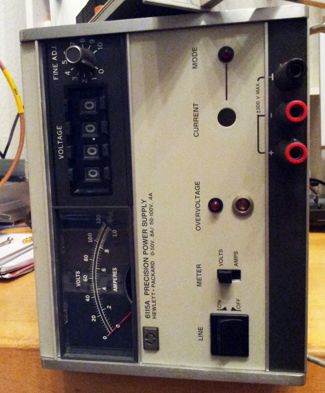
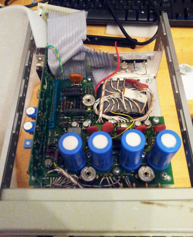
At least, it is a reasonable clean unit, and at a first glance, nothing major, like a completely melted board or smoking transformer. Judging from the soldering, someone already tried to fix it but gave up mid-way. Sure, I will not give up with this supply too soon.

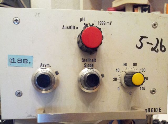
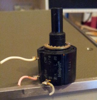
First things first – the current pot, a 10 turn 1 k, HP part 2100-1864 (Bourns 3540S): missing. Looking around in my parts collection – but no luck. At the very bottom of a stack of old electronics junk, a WTW 610 pH meter from the 1970s. This is used to convert pH electrode signals, to proper voltages, but even more important, it has 2 pcs 1k Helipot 7276 series 1 k pots. These are 20 ppm tempco, even better than the Bourns (50 ppm).

6115a-ph-unit

6115a-helipot-1k

6115a-front-view

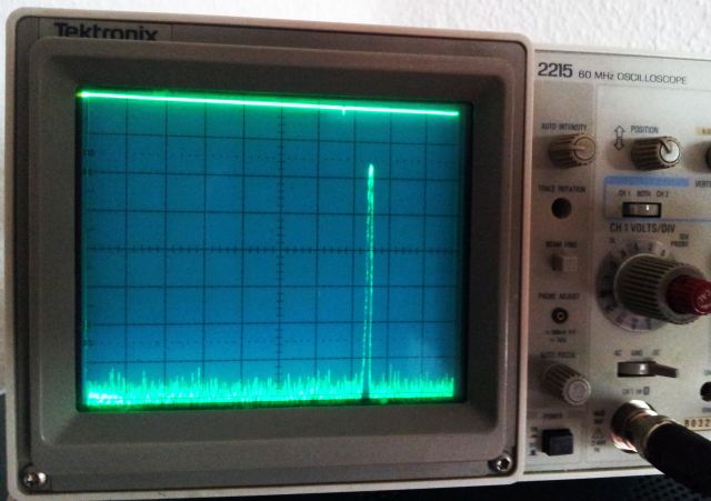
With the 1 kOhm pot fitted, still no function. About 60 V at the output, and the current limit LED lit, regardless of current or voltage setting.

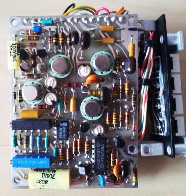
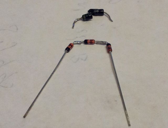
Looking around inside – a few issues found. There are several uncommon parts, like, a STB523 = 1N4830 voltage stabilizer, which is more or less a stack of 3 Si diodes. These parts are not commonly available anymore, so I replaced the defect regulator diode with a series assembly of three 1N4148 diodes.

1n4830-stb523-1901-0460

6115a-3pn-diode

Found a few more issues, several blown Zener diodes, all around the Q1-Q4 transistors. This is not good, because it may indicate some blown power transistors. And if fact, it did not take long to find out that Q1 has a full B-E-C short, and Q4 is C-B short, E-C, E-B open. No wonder that this disturbed the bias network Zeners, VR3, VR4.

6115a-dead-transistor

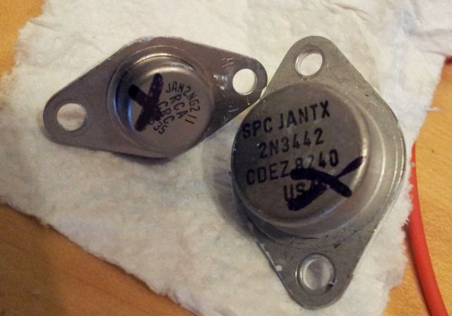
The transistors, 2N3442 NPN (Q1-Q3), and 2N6211 (PNP, high voltage power TO-66), at least the latter, not quite common – on order from an xbay seller in Greece, 5 EUR a piece of old and obsolete part, OK!
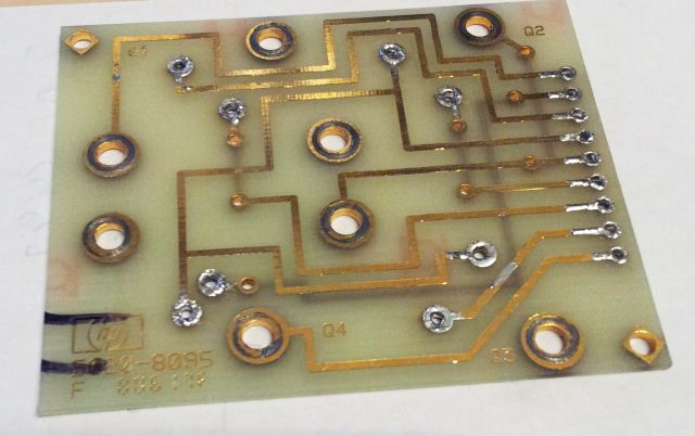
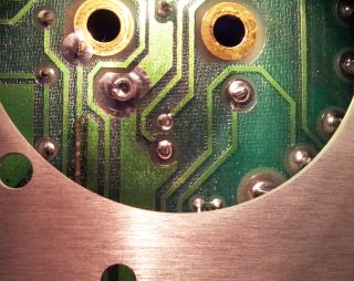
The power transistor board was an awful mix of bad soldering and flux, finally, cleaned and most of the solder removed.

6115a-pwr-transistor-board-cleaned

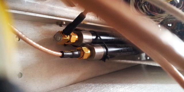
Found another defect – no voltage on C8, one of the main capacitors. Reason: a blown trace, from tap 16 of the transformer. Temporary fix with a yellow wire….

6115a-trace

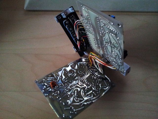
After some repairs, at least the basic voltages and supplies are up and working again, all capacitors tested, and working fine. Also reviewed the regulator board and its voltages (not shown in below diagram, red cross means dead part removed, green cross means part absent but tested good), all is fine and working.

6115a-reg-schematic-annot

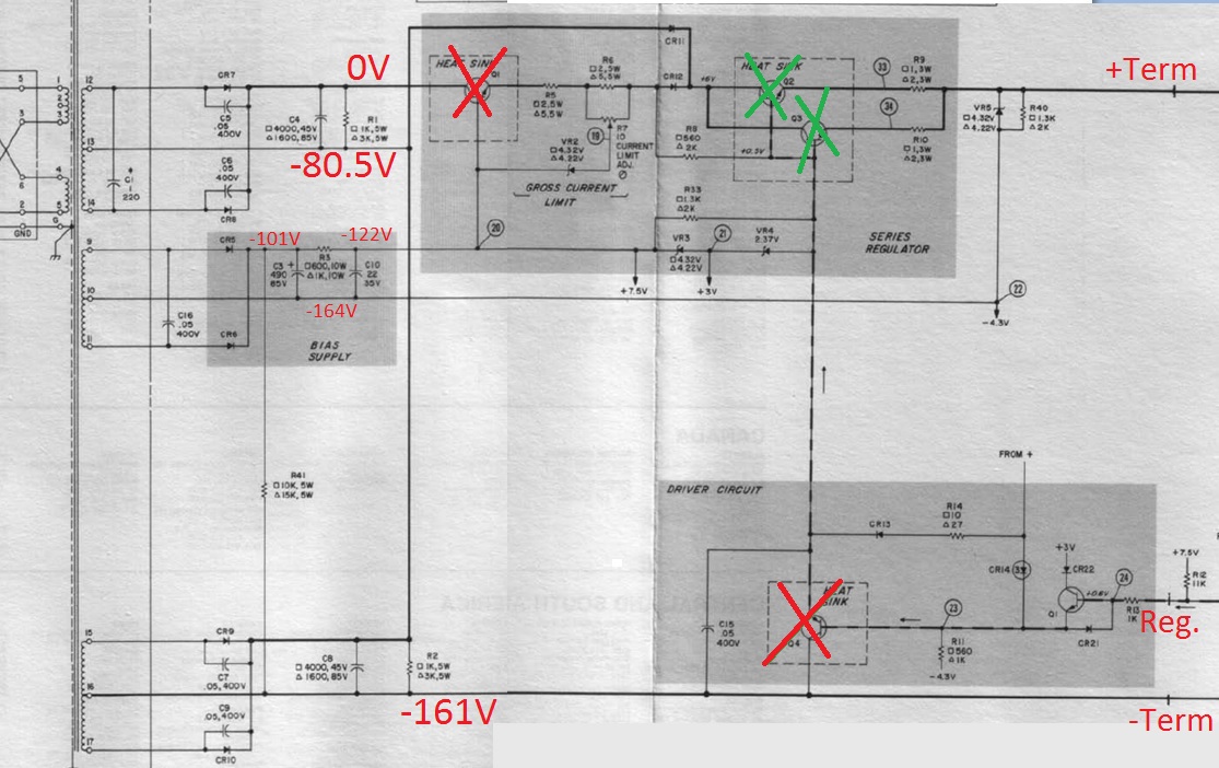
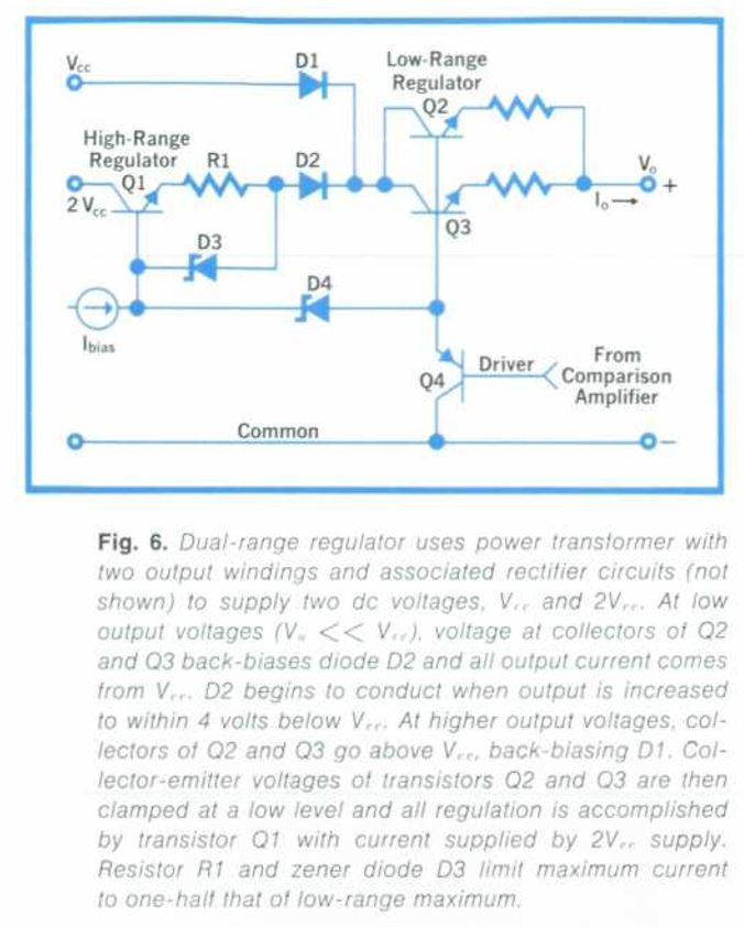
Note the working principle of the series pass regulator – it is a dual range setup, with a high voltage regulator, Q1 and the low voltage regulator Q2/Q3, all driven by the common Q4. Diodes CR11 and CR12 (a dual-diode element) is directing the current from the appropriate transformer DC supply (2 equal DC voltages of about 80 Volts are generated from two separate windings).

6115a-two-range-regulator

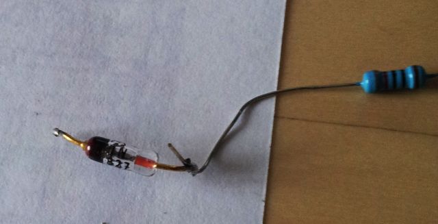
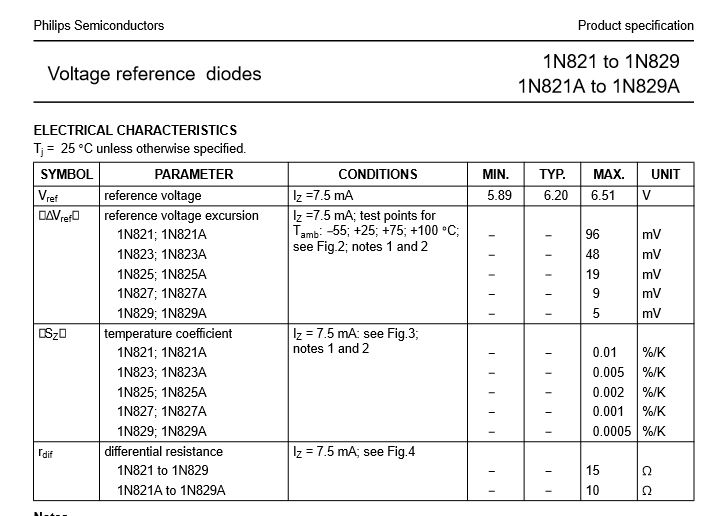
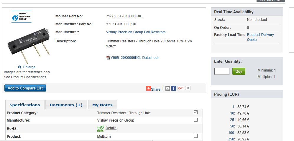
Apart from a 1N829 0.0005% tempco temperature compensate diode, there is another remarkable part used in the circuit, a 10 ppm 10 turn trimmer – not quite cheap, and still available today!

6115a-trimmer-10-ppm

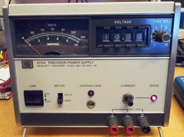
This is the current state of the instrument, waiting for the spare transistors, before I can put it back together, and hopefully, put it back in service.

6115a-board-top-view

Micro-Tel MSR-902C Receiver: root cause analysis, and a volt meter

Finally, some time to deal with the MSR-902C repairs. After replacing the 7401 TTL, and a 7404 TTL, the band select logic seems to work well, except two bands. This could be traced to a dead transistor on the A3A5 band control board. Still a mystery, what caused all these defects? Tracing the line going to the dead transistor (which appears to be a simple +15 V on/off switch), it only goes to one place – a circuit far inside the receiver. As it turns out, this is a hand-wired circuit, not really a circuit board, but a piece of sheet metal with various solder posts. And, on the other side, two filter. One filter mounted properly, the other tied to it with some thread. As you can see, this holds the filter in place, but it can still move around the other filter – and cause a short on the 15 V rail, including the signal coming from the transistor switch.

902c-moving-filter

902c-filter-short

To avoid similar defects in the future, I put some plastic sheet around the filter, and fixed it in place with better ties.

Finally, time for some alignment of the YIG filter, by using a fairly complex setup, a microwave signal generator, a scope to test the receiver output, etc. – see below picture.

902c-test-setup

The YIG filter needs to be aligned for each band, same for the YTO band edge frequencies. This is all done on the A3B7 board. Not much adjustment needed, fortunately, only some fine tuning of the YIG preselectors.

902c-receiving1

Receiving… quite fun to operate the receiver, easy to tune over the full range of frequencies. Maybe this is what makes it so suitable for detecting microwave bugs.

902c-receiving2

Some last repair relates to the frequency display. It did work in some bands originally, not sure how the defect came about – maybe I slipped with a screwdriver, or some other mishap, or some already damaged part, I can’t tell. But now it only shows erratic values, and without a schematic, it is a tough task to fix it.

902c-voltmeter-board

A fairly complex assembly, keep it mind, it is just a volt meter for the frequency display… so much easier nowadays…

902c-voltmeter

The LED display: hand-wired with Teflon coated wires. Sure, this receiver was never intended for the layman, but for some agencies that don’t care about cost and taxpayers’ money.

902c-handwired-display

After some tests and checks – the voltmeter uses a voltage to frequency/time converter, and a MIC5005 integrated timer! Quite a nice and complex chip for its age!

902c-mic5005c

Two hours later – found the issue. A bad reference diode, 1n821. Unfortunately, no such diode in stock, but it is quite similar to the 1n827, only that the latter is more precise, and more expensive, and only a used part in my bin. But easy to check, just put a resistor in series, and run at about 1 mA, and check the voltage drop over the diode. All good.

902c-1n827

902c-1n827-data

Finally, reception is pretty good over all bands, no detail tests of noise levels done yet, but already now it is clear that this is pretty capable receiver, build with only the best components at a time – just the style is not quite service friendly.

Demodulators work as well, receiving 1 kHz demodulated signal, all looking pretty good and clean.

902c-1-khz-test