SMEG CS19ID-6 Range: cold food only….

Recently, big disaster. My cooking range failed, not quite completely, but the right two of 5 induction hobs. It is not just a plain range, but a high end version large range, made in Italy…

It took a while to figure out how to disassemble it, and at a first glance, nothing visible, so I put it back together, and started to investigate the professional repair services…. quotations ranging from 900 EUR minimum, to 1500 EUR average cost to fix the error “E-5” that is now showing on the display.
Before going forward with the repair, I got some single hot plate so that at least cooking can continue, while dealing with a potentially lengthy repair.

A proper repair is done in a workshop, so I took out the whole hob assembly.

Upon close inspection, the filter assembly has a blown trace. It is a PCB trace acting as a fuse…

The copper of the trace deposited on the plastic cover nearby.

Fortunatly, the manufacturer, E.G.O. (a very famous German enterprise that makes most of the European induction range drivers) provided already a fuse holder to fit a US type 20 Amp slow-blow fuse.

Checking around, the left two IGBTs, IXGR40N60C2D1 are completely short.

That’s the full assembly, 74.470.061, with capacitors, a rectifier, and 2 IGBTs per hob.

For the time being, waiting for spare parts (ordered several more spares, and several fuses, just in case….). The IGBTs desoldered nicely, and I also checked the rectifier and all the diodes around, nothing suspicious.

Micro-Tel SG-811 Swept Signal Generator: another dead LH0021, and a design issue

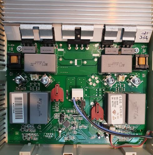
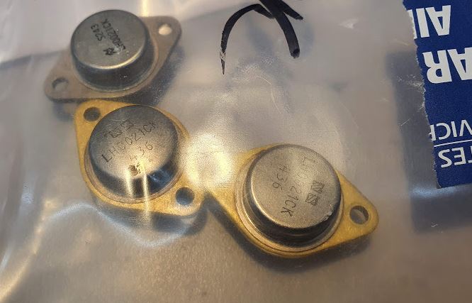
After only a few hours of use since the last repair, the unit started to play up again. Simply, no output on all bands. A quick check revealed the issue, fortunately, no failure of the power supply, but again, the driver board for the oscillators, and again, the LH0021 power opamp isn’t delivering current.

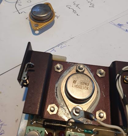
By removing the wire that connect the LH0021 output to the YIG tuning coils, and feeding current from an external supply, all working great – fortunately. With no other stock at hand, I decided to move the power amp LH0021 from the (not normally used) filter driver board to the oscillator board, these boards are essentially the same design.

After that switch, it worked again – but only for another 30 minutes, then it failed again, another LH0021 burned out. How can it be??

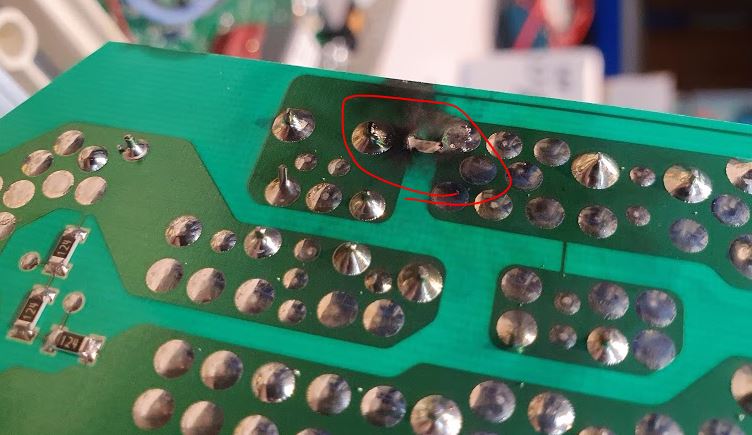
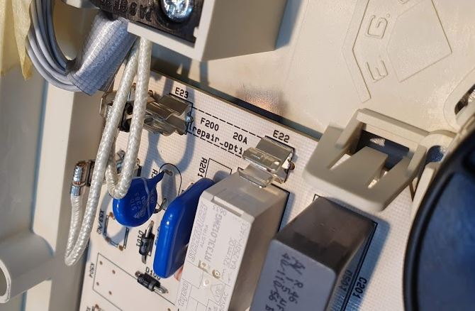
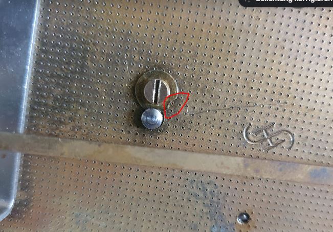
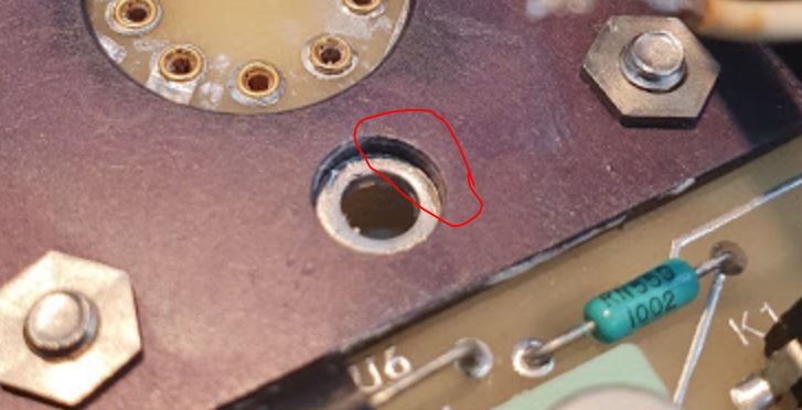
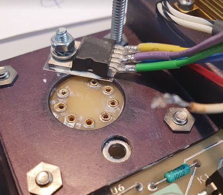
No, I took all apart, including the mica washer, suspecting some short through the mica or similar issue (the heatsink is ground, but the case of the LH0021 is output). The mice is OK, but there is an issue with the screw hole and its plating. On the top side, is is plated as much as that it contacts the heatsink just slightly, probably, when it expands with heat, it causes the deadly short. Noteworthy – the driver board has the top side of the screw hole completely unplated!

Anyway, too many defective LH0021 yet, and this time I couldn’t find a cheap source. And not willing to pay USD 20 and take more chances for these parts to fail.

As luck would have it, there are some audio amps in my stock, quite common in lower-cost stereo amplifiers. About 20 W audio power, in an easy to use TO220 case, and despite being obsolete, these are ubiquitous, and low cost.

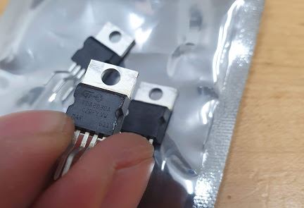
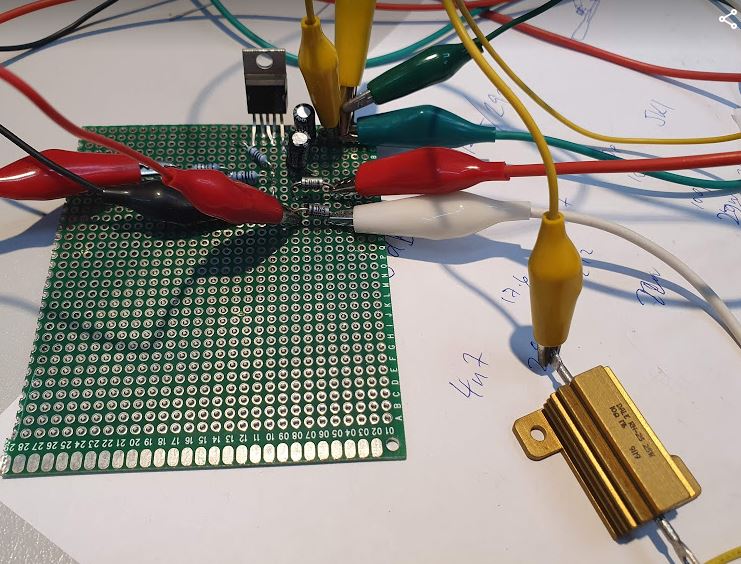
Normally, these are AC-coupled at input and output, and I didn’t find much reference to DC coupled uses. So I set up a little test circuit, and in fact, it provides a nice power opamp (unity gain stable).

Furthermore, the TDA2030 has both short-circuit and thermal overload protection. I wouldn’t call it indestructible, but chances are, that it would survive some adverse conditions.

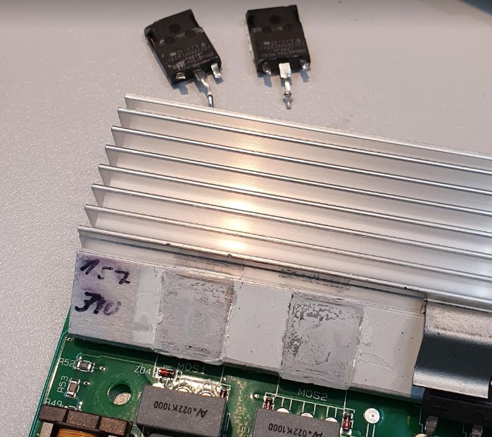
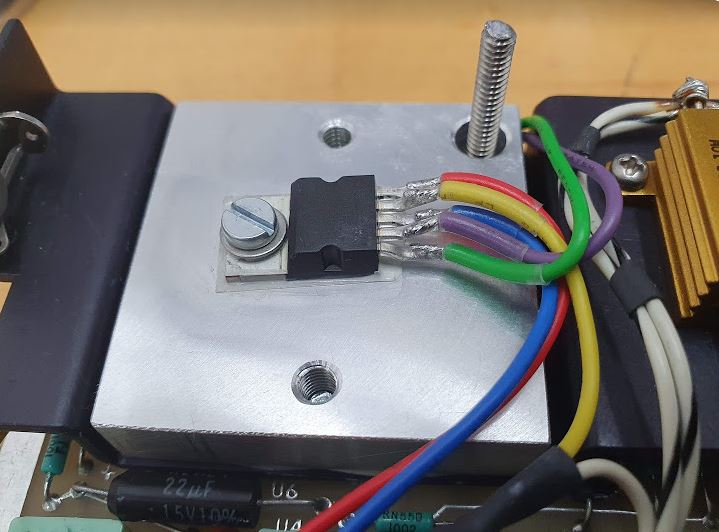
Only trouble, there is no good space to mount the TO220 case to the heatsink. But a temporary setup will do for now.

With no other change of the circuits, all seems to work well, and also the frequency response seems OK. The LH0021 has about 15 kHz bandwidth, this can be easily met by the TDA2030A.

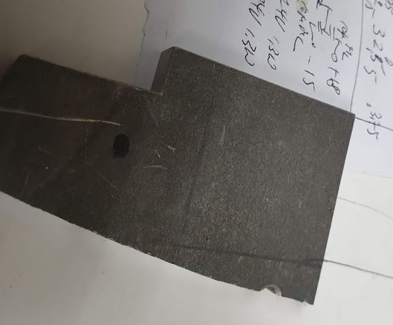
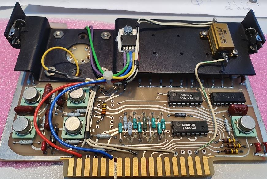
And in fact, it works well in the SG-811. All working and no need to align anything. Still, I would like to make sure the device has a proper heatsink. So, from a piece of scrap aluminum alloy plate, I machined a heat distribution plate, about 10 mm thick.

That’s the ready-machined parts, degreased with a bit of alcohol.

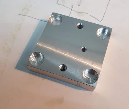
The distributor mounted well to the board, I cut threads into the metal block, so it is easy to affix to the board without any additional holes or modification.

To be not again trapped by some strange things, I also did some testing of the inrush current, power-on behavior and such (a current spike or reverse voltage may also damage the power amplifier). Also, mounted two more caps to the rails, and a dual-diode 48 V limiter.

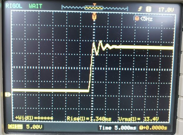
However, the startup of the 18 V rail is good and clean.

Same fix applied to the filter board – there is enough space to fit the amplifier without any trouble.

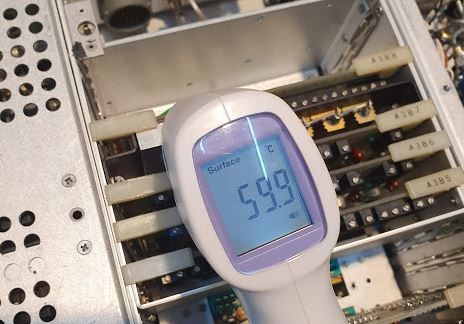
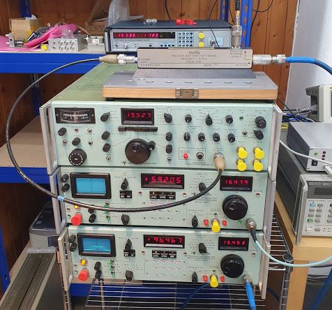
Running at 18 GHz for a while, the temperature stabilized at about 60 degC, well in the range of good working conditions. A few hours later, the SG-811 is still working. So, with some luck, hopefully, a permanent repair.

ADF41020 PLL: mysterious failures, and a not so mysterious fix

For years I have been building PLL microwave frequency stabilizers using the marvelous Analog Devices ADF41020 circuit, however, while in all permanent installation there were never any issues, occasionally the inputs failed in my attenuator calibrator setup – essentially a set of two microwave receivers, a microwave source, and a ultra-precision directional coupler (Narda 5082) and a HP transfer switch.

A EIP counter is used to monitor the rough overall power level of the incident radiation, as well as to check the correctness of the frequency and providing the 10 MHz reference to the PLL system. Each PLL has a ADF41020 board as the key input element.

One day, I noticed some ground loop currents, and again, one of the boards failed. So I decided to dig into it and solve it once and for all. Strangely, the board of the generator had never failed.
Looking at the datasheet, there are input diodes that may be easily destroyed by DC current flowing into the ADF41020 RF input.

It can’t tolerate voltages below ground or above 3 V much, so it is quite clear that some ground loops or other potential shifts can destroy it.

Further investigation showed that the RF sample output of the Micro-Tel SG 811 generator actually is AC-coupled (there must be some decoupling within the directional coupler that is getting the signal out, or in the switch leading to the sample output – which is quite possible because there are PIN diode switches inside that normally need DC blocking caps to work). The Micro-Tel 1295 receiver however have the center pin of the RF sample output connected to ground via a 50 Ohms resistor at the other side of the directional coupler taking some power off the line. So it is at least clear that the DC current from the center pin caused the ADF41020 to fail. Easily solved, added some 2.2 pF microwave caps. These are tiny parts, 0402 size, and remarkably cheap for their performance.

Soldering needs a steady hand, and definitely you don’t want to put a lost of stress on the board, which is mounted by the SMA connector only. Probably it could be made more rigid with epoxy, but I rather like to treat such PLL equipment and microwave gear with great care, because these are solid structures, but don’t handle impact and bending well.

After put all back together, so far no failures at all.

Siemens Electric Master Clock: after some years, a little repair

My trusty Siemens master clock, after some years of service without any trouble, it needed repair. The electromagnet coil that charges the weight, it is triggered by contacts that got dirty over time. So I cleaned all well with contact cleaner and some ultrafine abrasive paper.

With these little repairs complete, the clock showed another issue. It just stopped after some random time, and that is no good for a Master Clock. Generally speaking, pendulum clocks that stop oscillation randomly are difficult to fix. It may be dirt in some gears or bearings, it may be incorrect adjustment of the escape wheel, it may be some local disturbance.
Fortunately, the full clockworks can be removed without touching the Invar pendulum.

There are connectors at the top, well large in size, and with some silk spun wire.

Upon closer inspection, one of the main gears, which also drives the minute hand, showed issues. It is not fixed in position, but moved in and out. How can it be? When it gets out too far, there won’t be any reliable force transmitted to the pendulum, so it will eventually stop.

There is a washer, brass, on the back side of the movement, and this is supposed to hold the axle in a fixed position, while allowing it to spin freely.

Somehow, this washer had worn out. So I just rotated it.

Giving the clockworks a good clean and oil (only special clock oil made for medium-heavy clocks supposed to be used!), but without a full disassembly.

Now it is ticking away again, and showing the time, day and night.