Phillips Senseo Coffee Brewing System: the serious consequences of a broken wire

With close to 40 million sets sold, the Phillips Senseo coffee makers are in widespread use in various parts of the world, predominantly, Europe. Also at my workshop, this machine provides the essential supply of coffee. However, recently, this supply came to a sudden and unexpected hold, leaving me in a serious situation – stuck without coffee.

The defect was not related to any of the electronic or electric parts, but to the closing mechanism of the head part. It just would not close properly.

First we need to have a look inside. Using a screwdriver, the lid can be easily disassembled, by prying out the inner part with a screwdriver (needs to be done left and right).

senseo-head-dissassembly2

Inside, a broken wire spring, which is 1.5 mm in diameter, and made from some rather stiff stainless steel spring wire.

senseo-broken-wire

Where to get a spare wire? No 1.5 mm spring wire around here, but an old egg beater (maybe you can use some steel wires of an old umbrella?). So I decided to sacrifice one of its wires to the coffee machine repair.

senseo-wire

Here, you can see the wire installed. It is not quite 1.5 mm thick, but still, it works.

senseo-wire-mounted

After this quick fix, coffee again!

senseo-coffee-again

HP 83572A RF Plug-in 26.5-40 GHz: only a fuse away from the highest frequencies

Not one of the most preferred things to repair – a rather rare 26.5-40 GHz sweeper plug-in, not producing any output. Despite its rather simple function as a signal source, typically, not easy to fix if any of the microwave parts are faulty. New, close to 18 kUSD, so it is nothing you can easily replace from a hobby budget, and 26.5-40 GHz sources are not easy to come by.

40ghz-1

40ghz2

Inside, all full of heatsinks, and a few waveguides.

40ghz-waveguid

The modulator.

40ghz-modulator-45211h-2900h

The YTO. Not many companies around that can manufacture such devices.

40ghz-0960-0670-wj-5610-25

First thing to test, with no output present – the YIG oscillator. This has two main items: the bias supply, which is more or less just a variable voltage power supply which is tuned along with the frequency sweep. Secondly, the main tuning coil current, providing the magnetic field for the YTO. Checked both – and found the bias supply at 0 Volts. No wonder there is no output.

40ghz-a7-bias-assy-schematic

Upon inspection of the schematic, I noticed the fuse, which is rather hidden down on the motherboard. And, it was blown. No idea why – maybe just because of its age? Sure enough, HP did not use just any ordinary fuse, but a BUSS GMW model.

40ghz-buss-gmw

USD 9 per piece – that’s a steep price for a fuse.

40ghz-fuse

Cut the fuse open, and connected a 5×20 mm European style fuse. All protected by a piece of shrink tubing.

40ghz-fuse-replacement

Well, an about 1 hour later, the YTO is oscillating again, and you can see a nice and strong signal, well over 90 dB useful range, to test attenuators, or whatever 26.5-40 GHz device you want to put to test.

40ghz-transmitting

40ghz-receiving-again

Ultra-cheap LED Spot Lights: Failure mode analysis, and some reverse engineering, and some concerns

Something amazing about the advent of LED technology for general lighting is not only the brightness, efficiency, and so on, but also the amazingly low price. Here, 20 light fixtures, including 3 LED elements each, 34 EUR total. That’s a bargain a friend of mine could not resist. But think twice, after about 1 year of occasional usage of these lights – several failed. Brightness is gone, some lightly flashing lights remains.

led-20-pcs-33-eur

Still the price is amazing – considering the price of a singe 1 W LED element, with about 1 EUR retail. Plus the case, heat sink, aluminum circuit board, heat conduction paste, external case, 3 lenses!! No idea how this is made in China, for about 1.5 a piece delivered.

led-1w-led-price

The first suspect – the drivers: each lamp has their own little driver box. Type S3W-0103.

led-driver-case

led-spot-down-light

The parts, and a good quality aluminum board, named CQ-LV8072. This is a universal board, found in many kinds of Chinese LED light fixtures.

led-driver-cq-lv8072-board

Tested the LEDs – turns out, one of the LED elements is dead, and this ruins the whole thing, as all three LEDs are arranged in a series circuit. We can fix this easily by replacing the LED elements, all three, with some good quality elements. Albeit, at almost non-economic cost. Hint – the case and be unscrewed with the heatsink turning vs. the outer case. No need to apply brute force like I did, to open it up.

led-driver-s3w-0103-board

Some reverse engineering reveals a rather simple, but practical circuit. Using S8050 and MJE13003 TO-92 transistors, and a little transformer.

led-driver-s3w-0103-schematic

As you can see, no protection elements, what if the input capacitor shorts out, or if some overvoltage blows the transistor. Could it set your flat on fire? Well, my guess is, yes.

Digital Delay Line: sawtooth corrections of an ultra-precise GPS-reference 1 pps signal, and thermal effects

In an earlier post, I have already introduced the Motorola M12+ timing receiver, which is really a nice and affordable gadget for everyone who needs a precise and accurate time signal. Taking about nanoseconds here. All these timing receiver have something called a sawtooth error, linked to their internal clock. See earlier post: M12 perfect time.

Various methods exist to account for this sawtooth error, first and foremost, correction by software. However, I felt the need for a hardware solution here, to simplify the usage of the 1 pps trigger as a reference signal for phase measurements, and other purposes where the recording of sawtooth correction values would be rather troublesome.
With any such attempt at nanosecond scale, considerable thought needs to be put into the system to avoid introducing any errors larger than those we want to correct. In particular, thermal effects can lead to great long-term jitter, aka, randomly wandering phase.

How can we achieve compensation of the sawtooth error? Well, rather easily, by introducing a variable delay element in the signal chain, and adjusting its delay second by second, to the expected sawtooth error, in ns. Fortunately, the M12+ can be programmed to send out a message, called @@Hn TRAIM Status Msg, which provides, every second, the expected sawtooth error, of the next second. One single command is need to make the M12+ send out this message, very second, from now and forever, until other instructions received, or until the M12+ backup battery is taken out…

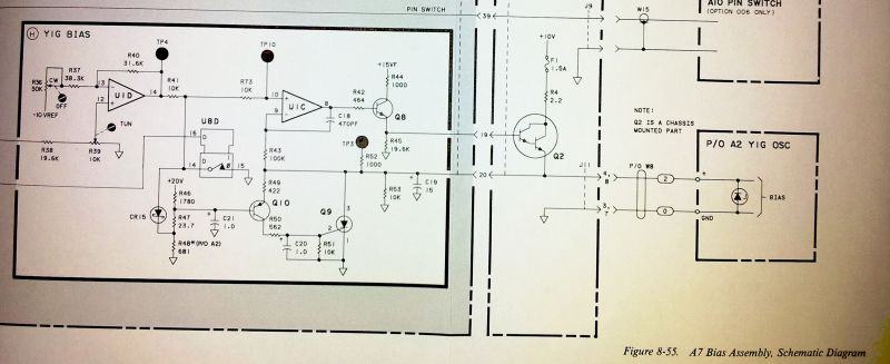
See below diagram, a AVR processor is tapping the TxD line, from the GPS receiver, to any host controller or PC (if connected), and whatever messages are send out are checked for the @@Hn message (and @@Ha message, just to display the current time, UTC, and date, on a LCD display connected to the AVR). Note that this works perfectly fine, even when another host, or PC is used to control/read/monitor the M12+. The M12+ uses 3 V logic, but an AVR input can easily handle this as a valid signal, even with the AVR running at 5 V.

dsdelay-rs232-controller2

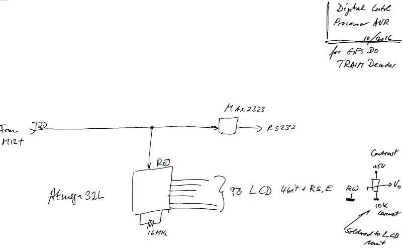
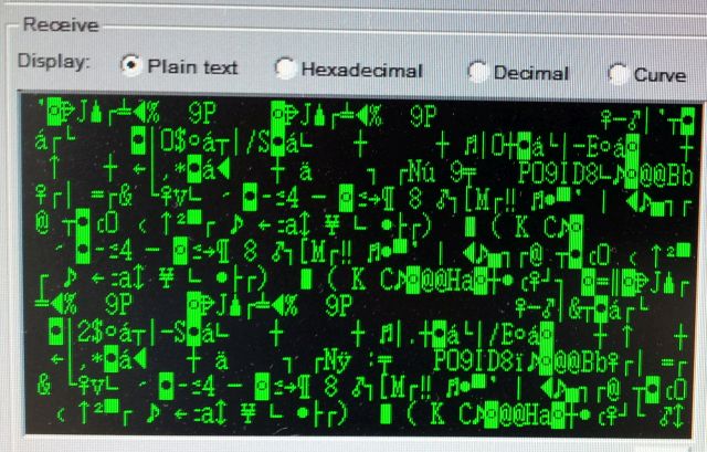
Glad a processor is doing the decoding work… the GPS messages, a bit too cryptic for me:

gps-messages

Rather than implementing a discrete solution with various delay lines as coax cables, switches, etc, Maxim Integrated provides a marvelous chip, a silicon delay line, DS1023 series, at not marginal, but still acceptable cost, USD 8 per piece.

dsdelay-ds1023-data-sheet

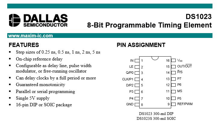
This chip comes in various versions, varying by the delay-per-set, and an 8 bit register, to set the actual delay. Sure, the minimum delay is not “0 ns”, but some odd number, corresponding to the delay of the signal before and after the actual delay line.

dsdelay-data-sheet-2

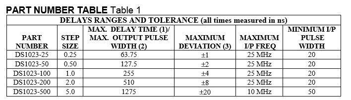
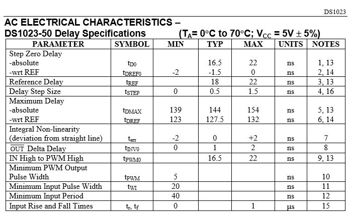
According to information found in the datasheet, this chip is trimmed for best accuracy, and high thermal stability. Further documents also say that the thermal drift is non-linear, and that no coefficient can be provided. Rather, the delay is specified as an absolute number, over the full temperature range. Well, fair enough, but what does this mean for our present case and actual device under test? With no information available anywhere, it seems, the only way to find out is to measure it. The datasheet maximum error would be a bit more than we want.

dsdelay-data-sheet-3

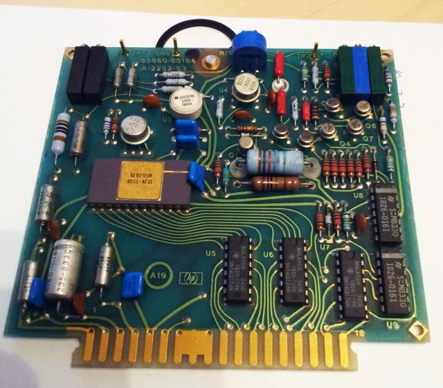
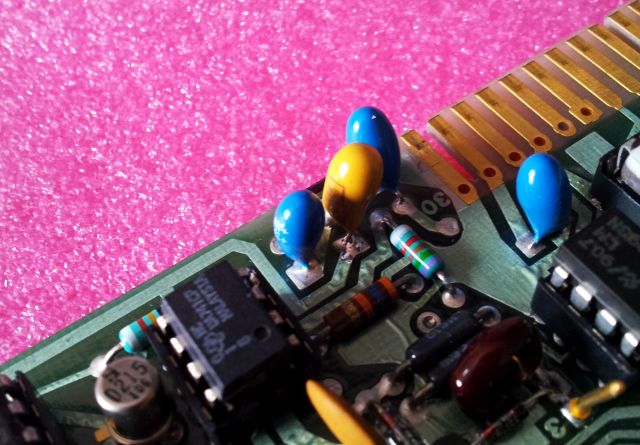
The schematic is nothing to write home about, a 74F04 is used to buffer the input signal, and a the same F04 is used as an output buffer, providing a nice and fast-rise (or, respectively, fast-fall) 1 pps signal.
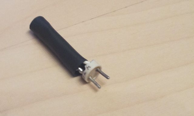
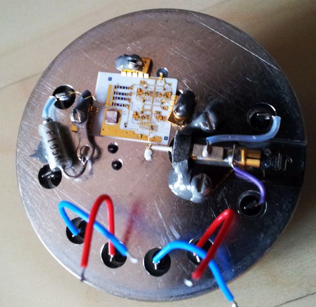
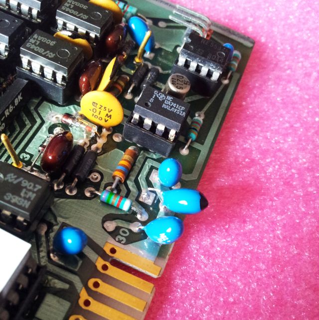
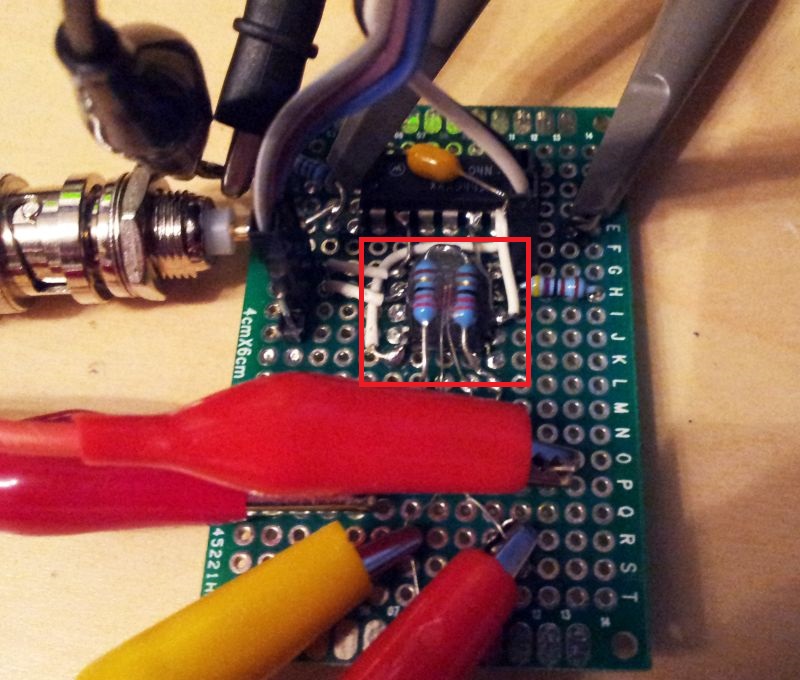
The only specialty, a thermistor, and two resistors epoxy-glued to the DS1023-50 top surface! This can be used to heat up the device rather quickly, to 60 degC or more, by providing power from a regulated DC power supply.

dsdelay-schematic

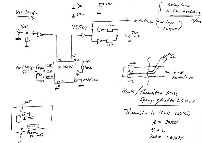
Note the heating element and the thermistor (a rather small, fast response, 100 kOhm NTC) – red frame.

dsdelay-board

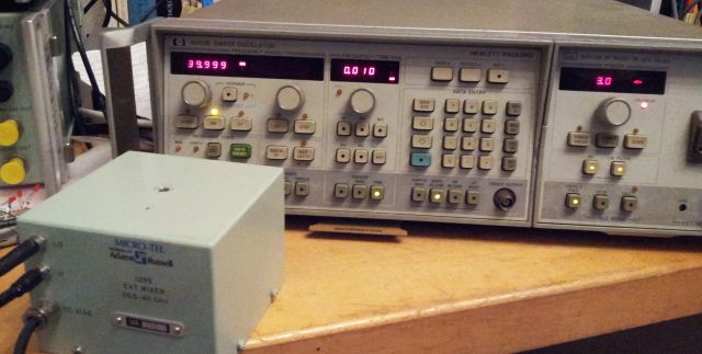
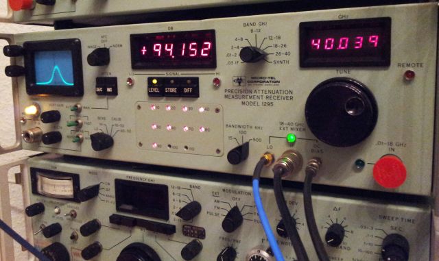
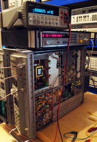
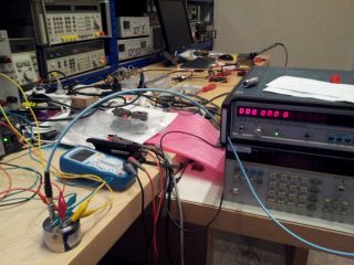
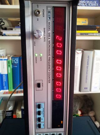
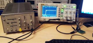
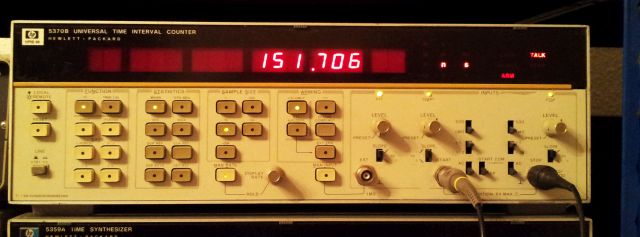
The test setup – to measure the temperature effects, is running without the GPS, but with a ~1 kHz fast rise-time pulse, from a HP 8012B pulse generator. Both input and output are connected to a HP 5370B Timer Interval Counter. The latter is a great device, single-shot accuracy of 20~30 ps, if you are into any precision timing tasks, very much worthwhile to get one of these, or a Stanford Research Systems SR620. Time intervals are then recorded as averages of 1k measurement, giving very stable readings with high resolution, certainly to 0.01 ns. For the test purposes, the AVR monitoring the RS232 signal can also be programmed via USB, to set any delay value from 0..255, corresponding to a 0..128 ns delay, plus any baseline delay of the gates and the DS1023-50.

dsdelay-test-setup

dsdelay-5370b-measuring

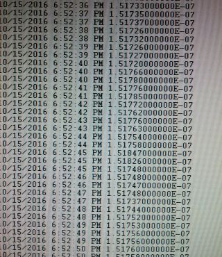
All connected to a PC via GPIB, and recording the delay values at various settings.

dsdelay-recording

Rather than many words, please inspect these diagrams, which will give you a feeling of the delay and drift to be expected with temperature cycling of the device at various rates (slow cooling, fast heating, slow heating, etc.). These were all recorded at the maximum delay, register set to 0xff, 255. Diagrams show delay, in ns, vs. time, as MJD.

dsdelay-temp-effect

dsdelay-temp-effect2

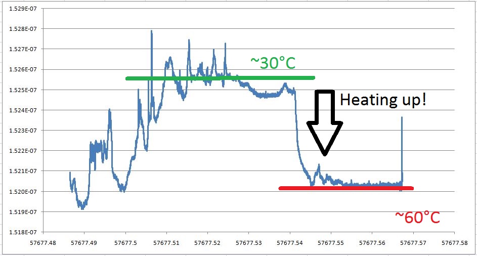
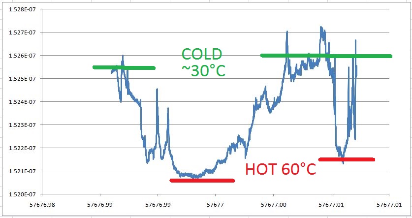
In absolute numbers, 152.1~152.7 ns variation. Not much. About 1 step. So maybe good enough, and no need to apply any temperature compensation, or to put everything into a thermostated box.

HP 8566B Spectrum Analyzer: A19 board, YTO unlock, bad precision trimmer(s)

Not the first HP 8566B on the bench, and not the first at all showing the famous “YTO unlock” message. Most of these YTO unlock message issues can be traced to defective capacitors, but not this time.

With the 8566B, take my advise, don’t touch any of the assemblies if you aren’t really sure which one is at fault, it is a fairly complex machine. To troubleshoot, a microwave counter is handy, to check the LO frequency.

8566b-repair

Next, the PLL was disengaged by disconnecting the cable from the sampler/LO pll. Still, no good LO frequency output. This leaves two main assemblies to be checked, the LO pretune DAC, and the YTO driver assembly, A19 and A20, respectively.

Quickly traced the issue to the A19 DAC assembly, and luckily enough, had a spare one around, albeit, an older version. After swapping the boards, it was confirmed that the A19 assembly is really the faulty part.

8566b-085660-60164-a19-brd

8566b-085660-60212-a19-brd-old-version

Next – desoldered all the capacitors at one end, but, to my surprise, all useless work, all caps in best working order, even after 25+ years!
Checked various components, and finally, found some issue with the precision trimmers – seems a cold or aged solder joint. To be sure the the fix is as permanent as possible, all the trimmers were removed, the solder connections cleaned, and all installed back in. Easy fix, all working again.

With this unit, there was no intention to do a full calibration, but as an extra service, I checked the power at the reference signal outlet – see below. Quite amazing how accurate, and pretty sure that this unit hadn’t been at a cal lab for at least 15 years….. this is really a superb level of lasting precision and quality, and ingenious engineering.

8566b-pwr-ref-test

Avantek S081-0321 YIG oscillator: not oscillating at all

One of the best sources of microwave signals still are YIG oscillators/YTO. These do require a good amount of power, magnetic coils, etc, but provide stable and rather low noise output, and good modulation capability. Core element is a small YIG sphere, placed in a magnetic field.

However, for the current unit under investigation (from a 18-26 GHz frontend), type S081-0321, 8.0-13.4 GHz, all the magnetic field and effort is wasted – no output detectable at all, not even a faint signal (checked with various equipment). Knocking it with a (small!) hammer, no effect. Varying the coil current – no effect.
Current consumption on the 15 V rail is normal.

yig-test-no-signal

yig-s081-0321-defective

Well, with all the basics checked, what to do with such hermetically sealed unit, other than using it to satisfy my curiosity about its internals. Hope to trace the defect to some specific part.

But before we consider more destructive measures, let’s try to re-tune the YIG by slightly adjusting the YIG sphere. This is possibly throught the side opening, which is usually welded shut, but can be drilled up rather easily.

yig-adjustment-open

Still no luck, no signal, even after turning the YIG quite a bit.

To look inside, carefully removed the top weld seam on a lathe, and the you can pry the case open.

yig-osc1

What you can see is pretty straightforward, despite all the gold wires. There is an input voltage regulator, from +15 V rail, down to 8 volts (measured about 8.15 V), this is then distributed to the 4 active parts via resistors (the bluish elements). Voltage at the resistors is about 4.3 V, so all stages seem to be adequately powered and current flowing as usual. Still no signal. Also probed other parts of the circuit, with a thin wire, under the microscope. No obvious defect. The gold wires and contact point reveal a good amount of adjustment done by placing/removing bond wires as need to adjust bias currents, probably also frequency response, etc.

yig-osc-closeup

The coil – rather, the coils. The thick wire is the main tuning coil, which accepts 0.4~0.6 Amps, the small coil around the magnetic center pole is the FM modulation coil. This is for much lower currently but high bandwidth modulation. All is sealed and soaked with epoxy resin. Note the hand made labels which may explain the cost of these units if purchased new… looks like US style handwriting to me.

yig-internals-mag-coil

Well, seems that fixing this is beyond what I can do here with the tools at hand. So will need to look for a spare/used 8-13.4 GHz YIG/YTO somewhere.

EIP 545A Microwave Frequency Counter: another dead tantalum repair

It’s not the first fix of an EIP counter here, and I have to say, these units are still very useful tools around any RF and microwave workshop, despite their age. The unit under repair, judging from the date code of the parts, is about 25 years old.

The symptoms – the EIP is just not counting. Showing 000000 zeros in the display, but no count. To confirm, you can use the build-in test function 01, by pushing test-0-1, and normally the counter will show “200 000 000”. But no indication of any counting activity for the current unit.

First thing you do, checked all the rails, and turns out the 12 V rail is dead. Starting from the right, removed all boards inside. And soon the defect was traced to the A107 board, gate generator assy.

Checking with the schematic, there are several ceramic and one tantalum cap.

eip-cap-desoldered

Desoldered the tantalum, and it is no cap any more, just a short.
With all the various tantalum shorts repaired in the past years, there seem to be to cases, some tantalum go fully short and activate the power supply protection circuit, with little powder dissipated over the tantalum. This is the good case. Some other tantalum seem to develop a short with some resistance, leading to considerable power dissipated in the cap, causing stench and risk of fire. The latter more seems to be more common with SMD tantalums, for reasons unknown. Also, the tantalum story is one of the many reasons why you should design current limit circuits, and power supply protection circuits, even in low power equipment, especially, if there are any valuable components that you might want to protect from a power supply failure.

eip-cap-a107-gate-gen-assy

eip-cap-replaced

The 10 uF replaced, with a new orange cap, but same “drop” style.

eip-counting-again

After carefully installing the A107 assy back into the counter (take care not the damage any of the wires), all is good. Counting at 200 MHz with the test function 01 activated.