HP 4274A Multi-Frequency LCR Meter

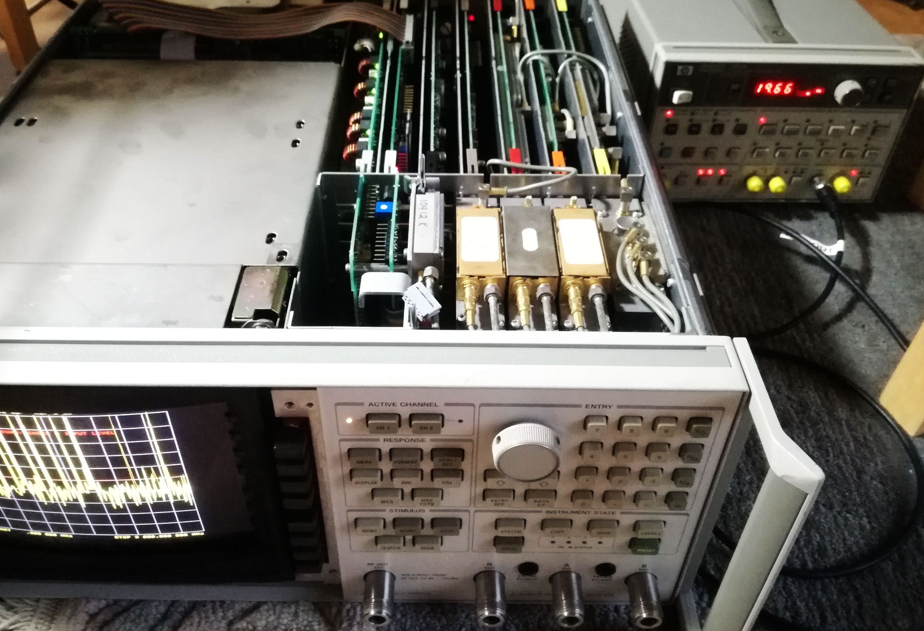
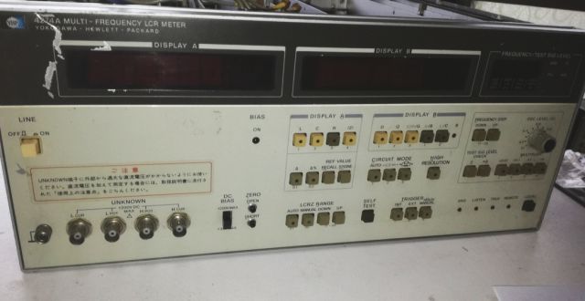
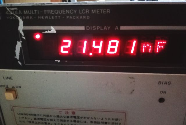
Nearly free of charge, we got this HP 4274A, in non-working condition. Unfortunately the former owner didn’t care much about it, so it suffered some front panel damage (optical damage only). Internally, it looks untouched, albeit, dirty.

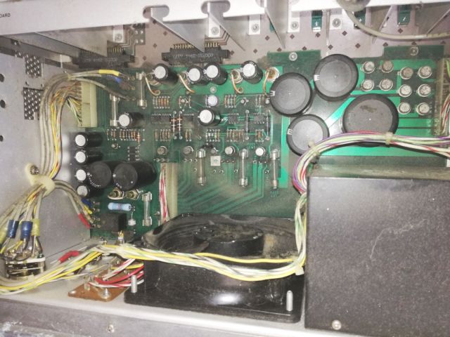
The power supply has a big fan with no filter. This will suck in air and dust. Time for some compressed air and a vacuum cleaner.

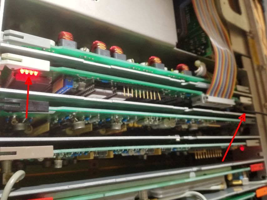
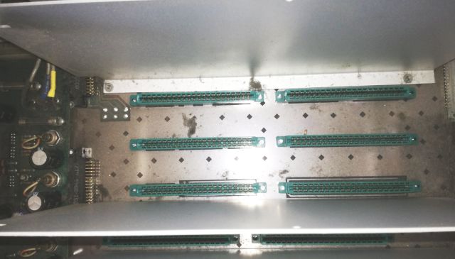
Also the card cage has some dust, better remove it before it causes issues when reparing-reinserting card.

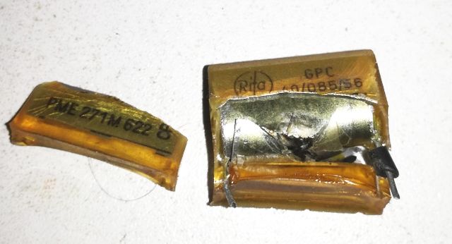
After the first power-on test, the common disease of these HP instruments, the X-rated capacitor blew up (Stink!).

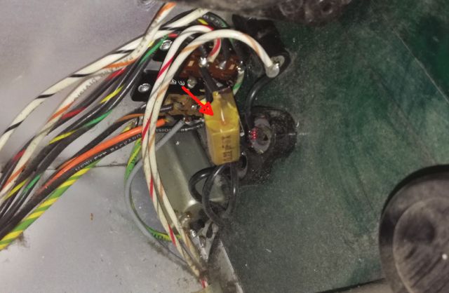
Again, the infamous Rifa brand capacitor. Replaced it with a new capacitor (make sure it is X/X2 rated!).

The symptons, there are many, (1) oscillator output has far too low amplitude, (2) something wrong with the range switching and amplifier chain), (3) with a all this, it won’t calibrate.

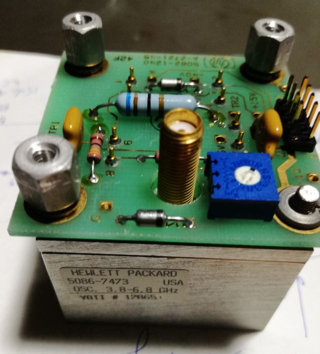
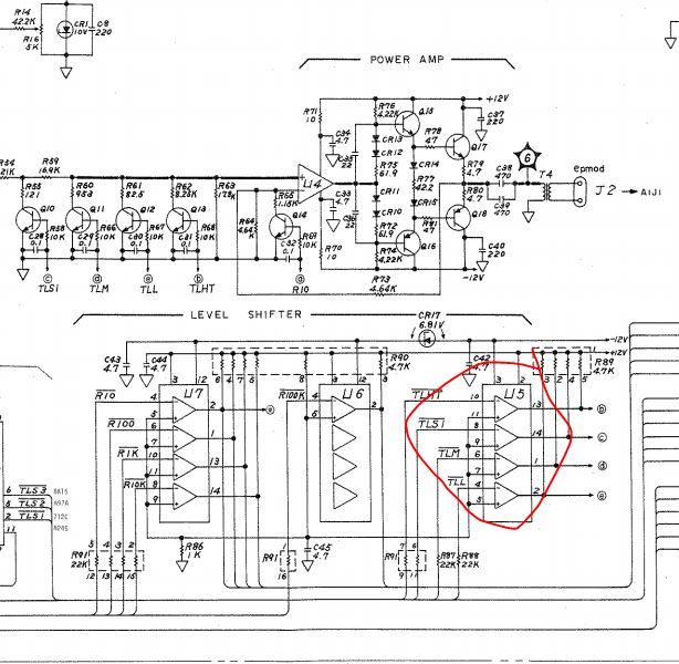
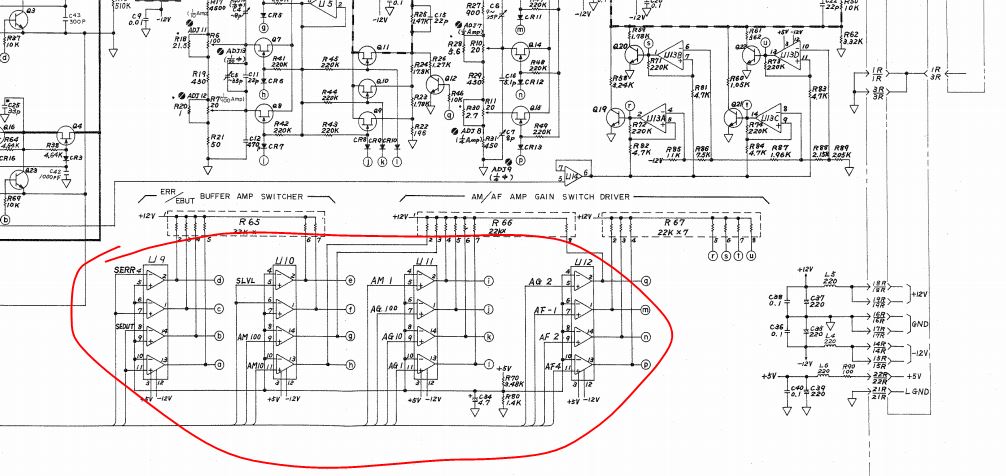
First, fixed the power amp, A6 assy (oscillator itself had no issues). Reason – a defective LM339 aka 1826-0138, so the range was locked on the lowest range of output.

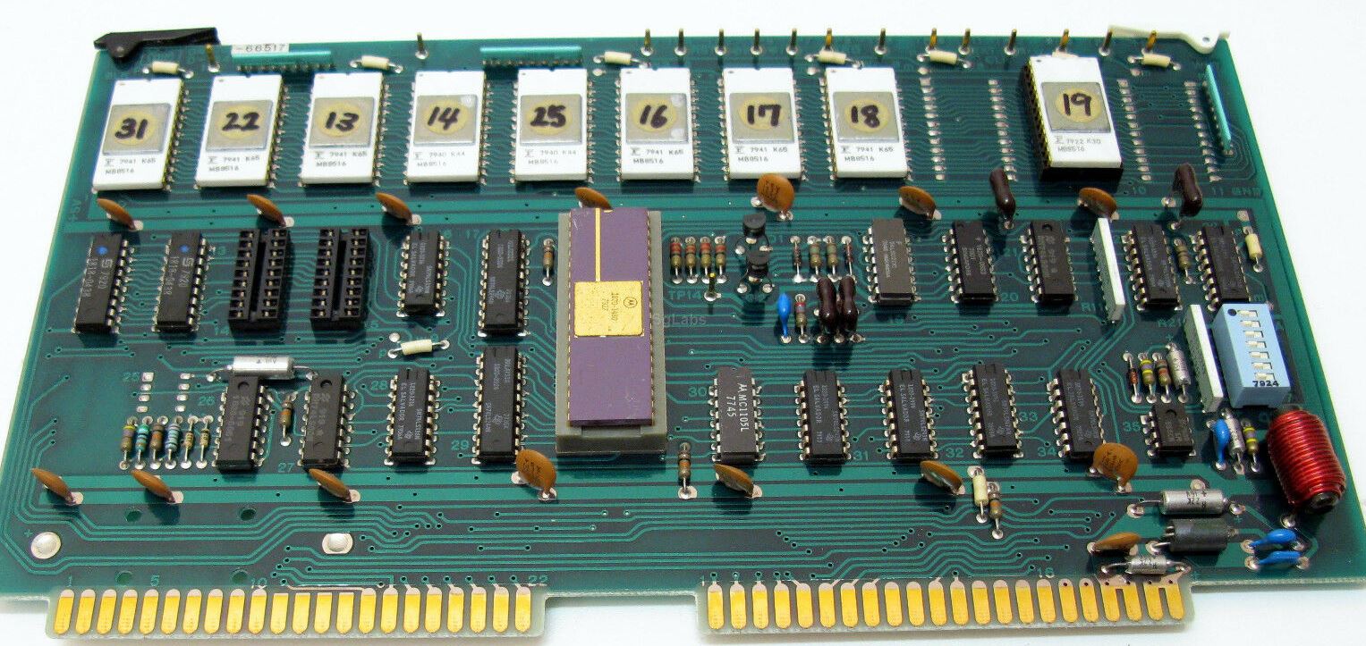
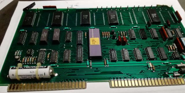
Another trouble on the A1 board, also there, a dead LM339.

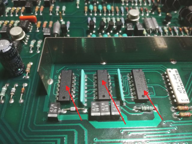
After recent repairs of several HP units of this era, there seems to be a real issue with the comparators, LM339, of this age and made my National Semiconductor. Many of them failed. Also, there are reports on the web about other HP equipment that had the same parts fail.

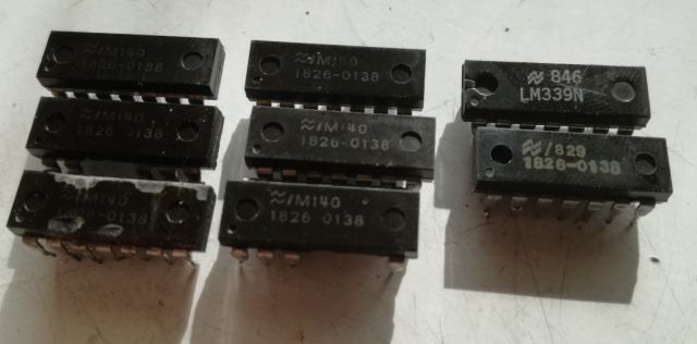
Eventually, I decided to replace all the LM339 of this 4274A, having found several dead. Just as always, my stock was 2 pieces short, so this will need to wait for a couple of weeks to get some shipped or to pick them up from the workshop in Germany during summer vacation (approaching soon).

For now, the unit is working fine on most ranges, at lower osciallator levels. At higher levels, there are issues because of incorrect switching of the process amplifier attenuator/amplification factor. This section is controlled by the two LM339s that haven’t been replaced yet…

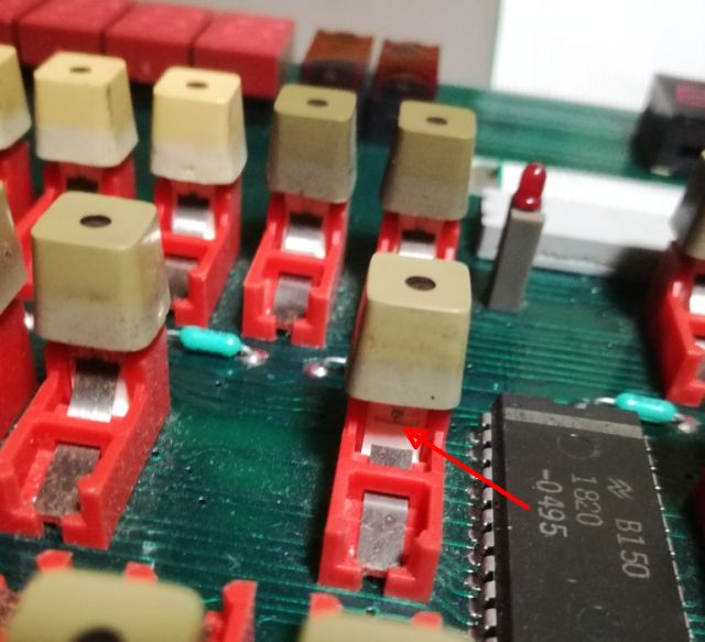
During the test operation I noticed one key not to work properly and decided to check it – the metal spring was broken, a small piece missing. Also this, a case for the spare part stock in Germany. Always check such defective keys, the metal springs and fragments may cause shorts and time consuming repairs down the road.

HP 8753C Network Analyzer: a dead FOX and a dead YTO

This will probably be a lengthy and complicated repair, because we are looking at a non-working 8753C. It is a great unit, in best possible shape, and came with all the original cables and a APC-7 test set. Even high quality APC-7 to N and -BNC adapters were included. Only downside – this unit is not showing anything on the screen.

Some quick checks later, found that the power supply is perfectly fine. Only, the A9 CPU assembly shows no activity. So I decided to take it out of the box, and power it with a lab power supply to see what’s going on. Absolutely nothing, no bus, no data. No clock??? Wait a minute. The clock is generated on the A9 assy itself, what can cause such silence? Probing around, absolutely no clock signal at all, not even at the osciallator (which is a standard DIL14 oscillator module, with the odd frequency of 19.6608 MHz).

Remove the oscillator, and it is completely dead.

Immediately, I ordered a couple of these oscillators at negligible cost, because I don’t have this cracy frequency in stock. To see what else is wrong with the unit, some temporary test with a 3314A signal generator (using the sync output). And, great news, the 8753C is starting up, with a very good and clean and focused display. The red arrows show the activity LEDs working, and the black cable supplying the clock.

Some basic tests later it is clear that the source has no output. It should sweep from about 300 kHz to 3 GHz, but no signal. The pretune DAC is working, also the driving signals are working fine (supply voltages and current). The source is all located in the A3 source assy. Made in USA, while the rest of the machine had been made in Japan.

There can be 4 issues with the A3 assy. (1) something with the control board, (2) something with the microcircuit, really bad, (3) the fixed oscillator, ok, (4) the YTO yig tuned oscillator, intermediately bad – can be replaced with a spare YTO but these don’t come cheap.

Test the fixed oscillator – always good to have all kinds of cables and adapters around!

For such tests, best use the pretune mode – disable the PLL. You should see good output with variable, slightly noisy (no PLL) frequency.

Next test, the YIG itself. Fortunately, we have the pinout from some old HP schematics.

No good news – no signal. I even opened it up, but no visible damage (except a kind of low cost construction YTO, and very thin gold bonding wires). I suspect the main transitor is bad, not enough gain anymore to make it oscillator – a well known issue of these HP economy-type YIGs.

Replacement parts are difficult to get for the 5086-7473, and no wire bonder and special tooling here to put in a new transistor. So my best attempt will be to use a good high end Avantek YTO to replace the original part. Probably, this will need some tuning of the coil drive circuit, but the 8753C is fairly robust in this regard. Let’s see if we can accomplish this – it will need to wait until August, because the various spare YTOs are all in Germany, in the main workshop. Stay posted.

HP 4274A Multi-Frequency LCR Meter: some dubious ROM images

If you are servicing or owning some older test equipment (or arcade games, or similar), I highly recommend to take copies of the internal program, usually stored on a PROM, EPROM, or mask ROM. As long as these are socketed, no problem – still we need to be careful because old integrated circuits may have brittle legs, but in general, it is easiest to remove the memory from the board, and then read it with some good EPROM reader.

One of the early late 1970 versions of the 4274A CPU assy (part number 04274-66617) has this feature, easy to remove 16k EPROMs:

The above board, I never had one in my hands, it is a picture from the web, and as per Keysight’s website, there were several later versions. So far I had two 4274A’s in my workshop for repair, and both had the later 04274-66529 board. I can only speculate that these board were made in a larger set, because is features mask ROMs rather than EPROMS, and there is high cost to only make a handful of mask ROMs (one would rather use programmable memory)

Many times, for test equipment, it seemed that in the 80s the program code was considered like something that will never change or need update, and the memory chips were directly soldered to the board. This had clear reliability advantages (cost at this level was no argument for that kind of equipment, but sure it is great to just solder in the memory by automated assembly rather than manually programming them, and putting them into sockets), and time showed that the engineers of HP were right, very rarely the ROMs fail, and if they fail, it is because of some catastrophic other issue, like a massive power supply failure. Only in one case, the single-time programmable EPROMs used in the 3562A, these fail all too often and too early, probably this memory design or specific series has reliablity issues.

Despite all this reliability, we want to keep copys of the ROMs, but how to get access to the chips soldered to the board. Unsoldering is no option. Soldering in general, on old digital boards, we want to avoid – because it may take days to get it back to service if something goes wrong.

So, how can we proceed? Pretty easily, we just pretend to be the CPU, and read the data by replacing it with a microcontroller that sends the address and data information for each accessible memory location (16 bit), 65536 bytes.

The test cables, can be shop-made from some resistors with thin legs, and some jumper cables, and some heatshrink tubin.

Some of the CPU signals need to be set appropriately to get access to the memory, like the VMA and R/W signals.

The setup, a simple Mega128A board that has plenty of ports, a USB to RS232 converter (running at 250 kbaud).

The Mega128A continuously cycles through all the addresses, and transmits the data to a host PC.

After some cycles captures, i.e., with all adressess read several times, is is only a matter of a seconds for a small console application to generate the memory dump.

But then – some time consuming observation. From the Agilent forum, I have a copy of 4275A ROMs (hte 4275A is the higher frequency companion of the 4275A, and the first 3 ROMs are supposedly identical).
ROMs 2 and 3 were found identical to my copies – but ROM 1 has 2 different bytes. How come? Maybe a corrupted byte? -these are generally rare to non-existent for mask ROMs.

To resolve it, I had to wait for a 2nd 4274A to show up here, and very recently it did, so I took another ROM dump (you can also recognize it from the color of the lithium battery above). As it turns out, the two 4274A I had in my hands have identical ROM images, so either there is an issue with the image of the 1818-1134 = 04274-85041 so far found on the web(taken from a 4275A), or these two ROMs are not identical for the 4274A vs. 4275A, against common knowledge. Any case, below you have the validated 4274A ROM images.

hp4274a 4275a ROM 04274-66529