Micro-Tel SG-811 PLL – phase lock achieved!

Thanks to a rainy late afternoon (and evening), some success with getting the SG-811 signal generator phase locked. For external frequency control, the SG-811 needs a coarse tune voltage, to adjust the frequency to within a few MHz of the target. This is done using a DAC8830(=MAX541) 16 bit DAC and OP284 opamp to scale the 0 to 2.5 V of the DAC to 0 to 10 V required for the coarse tune input of the SG-811.

The SG-811 is run at a level of +5 dBm, and a directional coupler is used to get a sample of this signal (about -5 dBm) into a ADF41020 single chip PLL. The remainder of the signal is fed into a EIP 454A microwave counter, which also provides a 10 MHz reference for the PLL.

First, it turned out that the SG-811 uses a different voltage range (-3 to 3 V) for the phase lock input, compared to the Micro-Tel 1295 (0 to 10 V). So the 8904A was used to determine the phase lock input sensitivity (deviation in MHz per Volt). Some existing AVR code (the whole setup is controlled by an ATMega32L) was modified to fit the SG-811 requirements. This code has some nice features, including a self-adjusting coarse tune voltage. This is of great help because the phase lock input of the SG-811 only allows for a few MHz frequency shift, and during warm-up the generator can easily drift out of the lock window, if the coarse tune value is left unadjusted. Obviously, the coarse tune voltage is changed in very small steps, 1 LSB at a time.
Drop me a line if you are interested in more details.

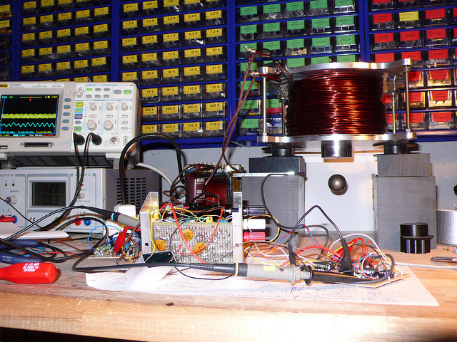
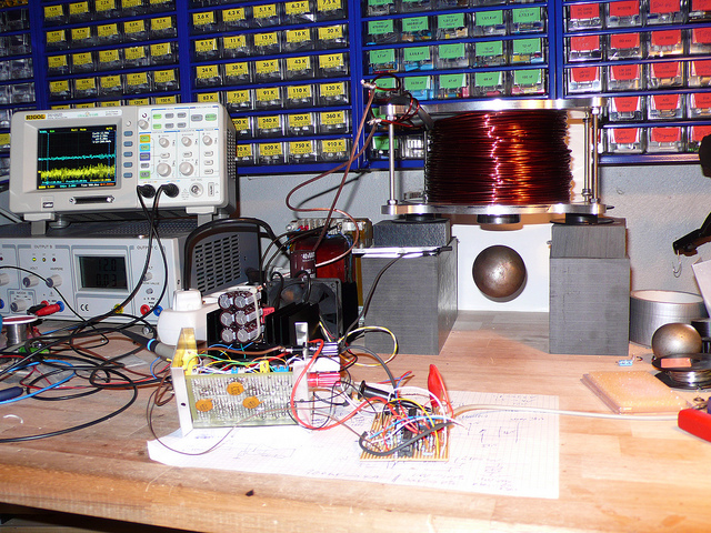
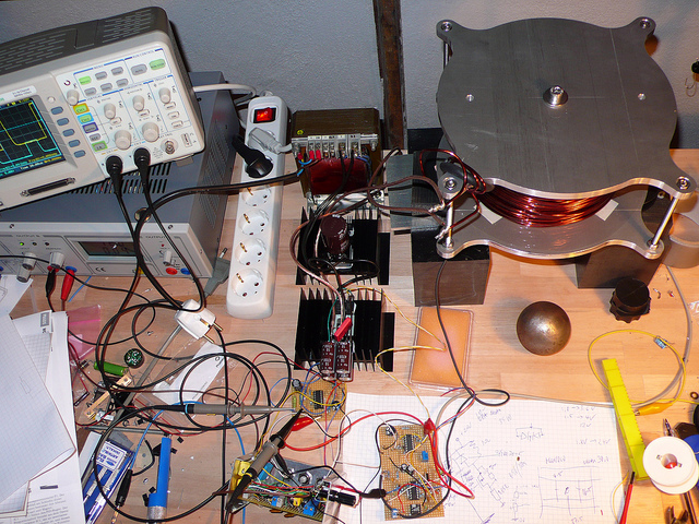
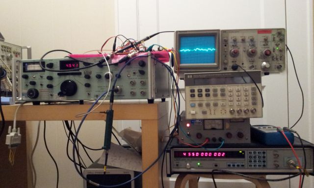
The (temporary) test setup, set to an arbitrary value of 4.5500 GHz.
20140831_223034o

The control circuitry
20140831_223151o
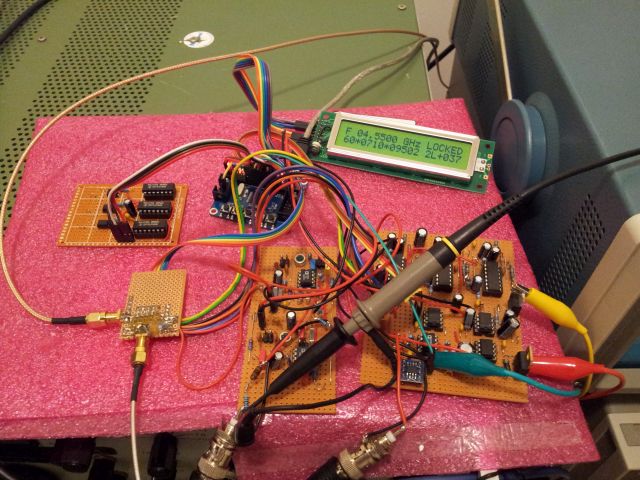
Display shows (second line): Divider values of the PLL, DAC coarse tune value (0 to 65535), band, and phase control voltage (deviation from mid-point in mV, +-100 mV are perfectly fine, if +-50 mV are reached with drift correction activated, the DAC coarse tune will be automatically adjusted to get the phase control voltage back to less than +-10 mV).

Last but not least, also the shift register board, 3x LS164 (for remotely controlling the band switches) has been connected to the AVR micro, and all is functional.

Solid state Tesla coil – aka “Plasma speaker”

This is really a nice project that any serious electronics hobbyist should tackle, or rather not, because it’s really dangerous, uses mains voltages, and emits undue amounts of RF radiation non-complient with all common regulations.
So please, take this for educational purposes only, don’t try at home, unless you are fully qualified, and have a shielded room, with no RF leakage to the outside world.

The test setup
3519200494_pl1

The coil
3518394491_pl2

The coil is made of about 0.3 mm copper wire (magnet wire), and resonant at pretty much exactly 250 kHz. A 2″ aluminum duct is used as terminal capacity, bent to a toroidal shape.

The circuit – it’s pretty basic. A SG3524 is used as the driver, with a 10-turn pot to adjust the frequency (to resonance). A small bit of FM (frequency modulation) can be provided from by an audio signal, fed via a pair of Cinch connector (sorry, no stereo – both channels are combined internally) – turning the solid state Tesla coil into a “plasma speaker”. You can hear the sound of your favorite song, played by hissing sparks, if you dare to hook-up you MP3 player to this apparatus (use a long cable, and an inexpensive player; don’t touch the player, when the coil is energized – you will radiate far too much RF into it!).
The SG3524 output is used to feed a gate drive transformer, which in turn drive the MOSFETs (2 pcs IRFP450, 500 V – 0.4 Ohm – 14 A). The low voltage part/driver is power by a little transformer, the IRFPs are connected directly to a DC voltage derived from the mains input, about 300 Volt (operating from 230 VAC in Europe). Don’t touch the primary winding!
Some VDRs, capacitors and diodes are used to keep transients away, and to keep it running stable.

The final device – it’s working great, but don’t have pictures at hand – will provide later! As I said, don’t try this at home, but I will gladly answer any of your questions.

Sparks!

I can tell you, these sparks are quite noisy! Keep you children (and yourself) at a safe distance!
Never attempt to energize such apparatus at your home!

4576009680_2ef5d63635_spark

With the given 0.5 mA supply, there is a spark every few seconds. Triggering is nice, and stage voltage reaches about 23-24 kV – the design limit.

Should you ever operate a Marx generator, make sure to properly ground and short it prior to approaching it any closer than a few feet!

Stage design

Some boundary conditions:

(1) Stage voltage equals charge voltage – 20-25 kV range would be most suitable to fit an easy-to-build flyback transformer type supply.

(2) Discharge energy should be at least 10 Joules, otherwise, there is not enough noise and the thing doesn’t look and feel dangerous enough (you might as well use a piezo fire lighter to make some sparks…)

(3) Charge time should be reasonable, not more than a few seconds.

With 16 0.1 µF capacitors, rated for 1.6 kV and operated at 1.5 kV (24 kV per stage), a design was established that uses 10 stages – about 220-230 kV peak voltage. This results in about 20 Joules of discharge energy.
It was also found that there is no need to make the stage charging resistors very large (some sources suggest multiple Megaohms, 1 M is just fine for most of the designs relevant in this context). A value of about 8 M was determined for the charge resistor – mostly because of the 0.5 mA current limit of the power supply – you can use a lower value, if you want to put more current into the Marx. But remember that a high-value charge resistor will also protect the rectifier cascade of you power supply, so you might not want to take too big risks.

Detail view
4575383663_3301c7552d_stage

For the spark gap – these are the approximate voltage for a gap mm:
voltage vs gap

Accordingly, the gaps were adjusted to about 8.5 mm using a plastic gauge (to avoid scratching of the spheres).
Note that the stage carrier plates have cut-outs at the spark gaps! This is to avoid unwanted discharge, but also to ensure line-of-sight contact of the spark gaps, which ensures stable triggering (because of UV radiation, emitted from one gap, lowering the spark cap threshold voltage of the next).

Full view
4575383663_3301c7552d_full
(in the back, you can see an earlier experimental model, using Wima FKP-1 capacitors – however, this design added a lot of inductance, and the adjustment of the spark gaps was not thought out very well).

The starting point

What is a Marx generator – essentially, a device that lets you charge a set of capacitors in parallel (say, to 24 kV), and then discharge they in series, say, at 240 kV, if you have 10 capacitors. There is much more theory to it, all has been very well described elsewhere since the times of Mr. Marx, who first deviced such circuits, arguably, in 1923. If you need more explanation – please ask, I will be glad to explain it to you.

To build a nice Marx generator, you need a few parts:

(1) High voltage resistors – don’t assume this is the easy part – the resistors need to be able to withstand quite some voltage, several kV, and high discharge energy-changes in potential. Carbon composite resistors are best for such applications, but rate to find nowadays. You can get away with series connection of some high-value metal oxide layer transistors. I used some Vitrohm 1 M (Megaohm), 7.5 kV rated resistors obtained as NOS (now-old-stock; series 176 – could not find any data, but seem reasonably robust), some current/more widely available types that may be suitable: Vishay 0207 High Pulse Load Resistors (2 in series), or similar, successfully used for similar projects of more serious nature.

(2) Capacitors – also these must be not only be designed for high voltage, but also pulse rated. Best are especially made pulse discharge capacitors – but these often are oil-filled, rare, and too big for the given purpose. Best alternatives are PP type film capacitors, like the Wima FKP-1 or FKP-4. I used Vishay MKP1841, 0.1 µF 1.6 kV capacitors, metallized PP. The spec to look for is the maximal pulse rise time – the 1841s are not too bad, at least, good enough for this project, and a large bag could be sourced at low cost.

(3) Spark gaps – these need to trigger precisely, otherwise, the apparatus won’t work at full performance, or constantly misfire. Best use polished stainless steel spheres, about 15-20 mm diameter, readly available, already threaded, and easy to attach to the stages.

(4) Some hardware – isolating stand-offs, and some isolating sheet material for the stags – I used some FR4 glass fibre-epoxy boards (leftovers from failed printed circuits, with the copper fully stripped).

(5) A high voltage supply and a feed resistor (about 3-10 M, capable to withstanding at least 50 kV). A series of resistors, item 1, mounted along a plastic rod (Plexiglass, or the like) will do. For the supply, this needs to provide about 20-25 kV (make sure it doesn’t provide more, otherwise the capacitors will suffer!), about 0.5 mA. A fly-back transformer based supply. I’m use a regulated supply (TL494 switchmode regulator, flyback transformer), so the stage charge voltage can be adjusted precisely, and no risk to damage anything.

(6) A good ground connection (earth conductor). Never use plain mains ground, if you don’t want to damage your home electronics! Anything will do, like a water pipe (if fully metallic down to the inlet), or a heating pipe).

(7) Plenty of ground wires around that you can use to safely discharge the apparatus and to keep it shorted to ground if not in use. RISK OF ELECTRIC SHOCK! ALWAYS SHORT THIS APPARATUS WHEN NOT IN USE!

The current regulator

The current regulator – this module converts the current setpoint signal (from the position regulator) into a drive current for the magnet coil. This is achieved using a TL494 PWM modulator chip, and two BUZ11A (50 V – 0.045 Ohm – 26 A) MOSFETs, each operated at 50% duty.

levi_current_reg

Brief description:
The current setpoint signal is connected to JP1-9, connected to one of the comparators of IC2, the TL494. The other comparator is used as a current limiter: the sense wires of a 0.05 Ohm shunt in the coil supply line are connected to the input of IC1, and intrumentational amplifier, via JP1-7 and JP1-8. You might have to change the amplifier gain by modification of R5.
Current setpoint is adjusted by trimmer R14. JP1-3 and JP-4 provide the gate drive for the two BUZ11A MOSFETs. The drains are connected to the coil, the sources are joined at the current shunt.
Directly, at the MOSFETs, which are mounted on a heatshink (but don’t actually get hot), together with current shunt, there are several electrolytic capacitors (low ESR type), and a 1 µF PP cap (polypropylene dielectric, for pulse current service) in parallel with the (non-regulated) magnet supply. In combination with a strong and fast Schottky diode (anode at the MOSFETs, cathode a the positive supply), these caps are the best protection against any transient voltages when the coil is de-energized.

The position regulator

The position regulator takes the output from the position sensor, and converts it into a voltage drive signal. Nothing fance-it is just an opamp implementation of a PID regulator.

levi_position_reg

Brief description:
The position signal is connected to JP1-8, and converted to a 0-referenced voltage, relative to the desired position setpoint (R13, 10-turn pot), using IC1A, 1B and 1C.
JP7-1 provides this shifted signal for monitoring (position error signal). Opamps IC2A, 2B and 2D for the proportional, differential, and integral parts of the PID regulator. The P-component is made user-settable via R14 – a 10-turn pot. The other components only need some initial adjustment, depending on the coil you are using (C5 and C8 might also need adjustment; use high-quality capacitors, Mylar or similar). IC1D sums all the regulator components, and has R12, another 10-turn used-adjustable pot for total gain adjustment. Total gain is the most critical adjustment, if you change the type/weight of the suspended part.
IC2C adds a constant offset-just to prepare the signal (available at JP1-3) for the current regulator. JP1-5 has the intermediate current regulator setpoint, for monitoring purposes.

The position detector

The position detector module senses the exact position of the object suspended below the magnet, using a modulated infrared (IR) light beam, and a frequency-selective phototransitor amplifier, and converts it into a voltage signal. The range is a few mm, so there will be a need to adjust the position of the detector, if you want to change the distance from the magnet.
The circuit is pretty fast, and can detect position changes in the range of a few micrometers easily, and at kHz bandwidth. Also, the output (voltage vs. gap) is very linear, this has been checked with the help of a micrometer stage, used to block part of the beam.

levi_position_sensor

Brief description – lower part, the IR emitter driver:
This part of the circuit uses one half of a 324 quad opamp – IC1D is running as an oscillator, and IC1C, as a current regulator for the IR emitter, a Fairchild QED233 (940 nm, 40 degrees emission angle, 1.5 A peak forward current). R11 is the current sensing resistor – a BUZ11 is used as a driver. The QED233 is attached to JP1-1 (cathode) and JP1-2 (anode). R12 and C7 de-couple the IR emitter supply, to avoid interference with the receiver circuit.

The upper part, the IR receiver: active element is a Fairchild QSD124 phototransitor (narrow angle, 24 degrees, IR diode with daylight filter), attached to JP1-5 (collector) and JP1-6 (emitter).
The phototransitor output first passes through a high-pass filter, R6/C3, and then through a rectifier, D1. The resulting signal is then low-pass filtered to remove the ripple (R8 added to reduce noise/oscillations), and amplified (IC1A). IC1B does some further clean-up, and provide a nice drive signal for the other circuits. R1 really serves no function other than being a handy test point for troubleshooting.

The coil, the circuits

Others have explained at length the theorical background of magnetic leviation, and the associated regulator maths. I don’t want to get into this here – feel free to ask, I will explain it to you.

The goal: an apparatus that can hold a sphere of at least 1 kg mass (about 60 mm diameter, 2 1/2″) suspended from the pole of the magnet, in a distance of at last 25 mm/1″. It should be adjustable to hold also other parts, and not restricted to magnets (many of the available hobbyist leviation circuits can only hold magnets).

With the goal set, and after some calculations, related to electric magnet, heat dissipation, allowable maximum temperature for free air operation, time constants – the coil: about 10 kg of copper, of roughly 3 mm diameter wire. I selected a high-temperature type W210 isolated copper wire, this will withstand long term use even if the coil is operated permanently at full current. Don’t worry about the space the 10 kg will take, copper is very dense… Winding it can be a bit tough, as always, ask a friend for help, and best wind it with the help of a lathe (by manually turning it), or some other makeshift fixture. Winding it free-hand is not a good choice, because you won’t get a nice and tight coil.

4838811106_6008111b04_z

For the circuits, these were build in modular style:

(1) The position detector – based on an infrared LED, and infrared photodiode, and fully independent of the lighting conditions. Is uses a modulated emitter, and a frequency-selective detector. It needs to have a reasonably fast response, and low noise/drift, otherwise, the regulation loop will be unstable – the sphere will start oscillating, and drop off.

(2) The position regulator – this is a classical PID regulator, build using a few TL074 opams. It compares the position setpoint and acutal position (from position detector, item 1), and determines the current needed to hold the sphere stable (current setpoint signal).

(3) The current regulator – this circuit converts the current setpoint signal into a drive current for the coil. To avoid undue powder dissipation in the regulator, this is achieved use a classic TL494 PWM regulation scheme. There is also a current limiting circuit, build-in, with a 0.050 Ohm 4-lead sense resistor in the coil current loop, and an AD620 instrumentation amplifier.

(4) Some auxilliary circuits – to switch off the magnets by disabling the current regulator, if there is no object attached. Otherwise, the magnet would run at full current, if the sphere drops off, and dissipate a low of heat for no good reason. Some power supply circuits – to provide 12 V power for the regulators, and unregulated 35 V to drive the magnet.