A nice offer from the famous “Shenzhen Hengxingxing Precision Instruments Co., Ltd.”, or, HXX in short, lured me into buying a “retro-style” DRO for my lathe. There are all kinds of touch-screen DROs available, and I have the lathe connected to LinuxCNC including a DRO display, but nothing beats the charm of 7 segment LED displays and some buttons in terms of productivity and handling convenience in a workshop with oily and dirty hands.
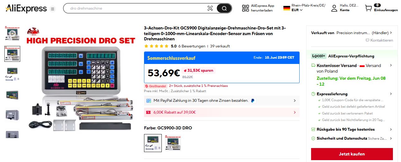
The offer, just a little over 50 EUR, shipping from Spain – so there is no risk of customs duties or value added taxes and similar, all is included.
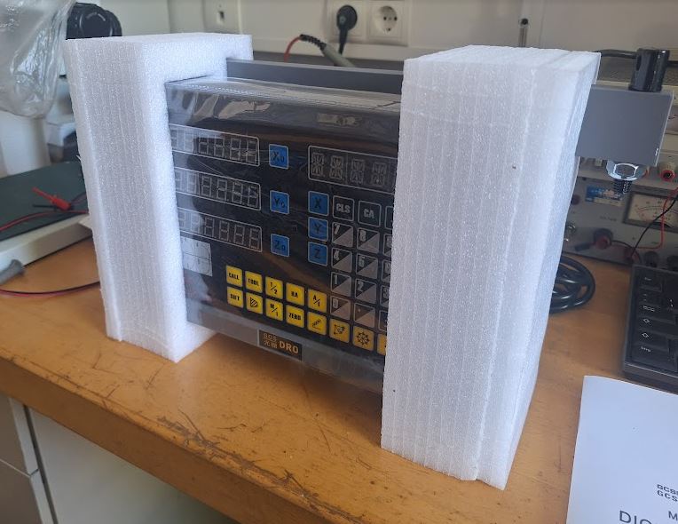
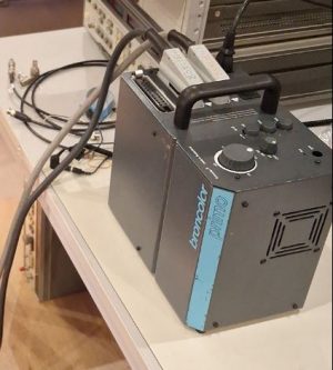
The device came well packaged, in a strong box, with foam padding, in a plastic cover. A paper manual is included.
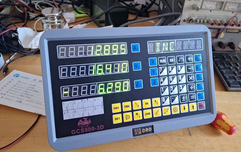
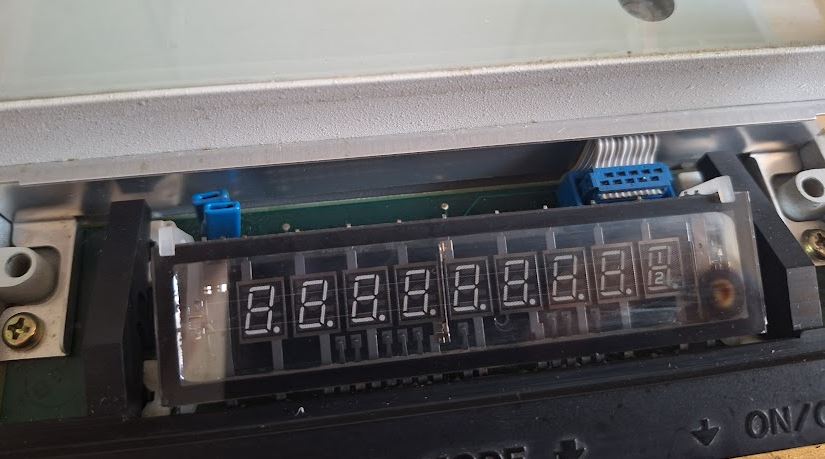
Surely, I needed to open it and check it out before use. There are three 8 digit displays (XYZ) and an 8 digital alphanumeric display on top. Many function keys and a build-in calculator, so we don’t have to scroll through some menus but can access each function by pushing a button the old school way.
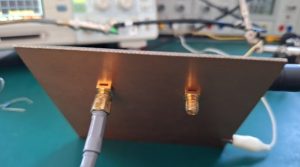
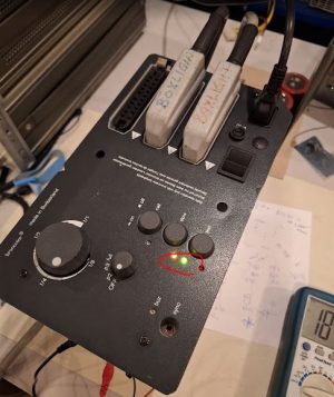
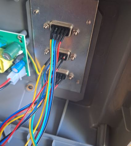
The connectors are wired for a typical Chinese DRO pinout: Pin1 5 Volts, Pin 2 Ground, followed by A B and Reference. Sino and other common brands use different pinouts, but you could easily solder the wires as you like. There is a metal plate that holds all the connectors, so in very special cases, it is even possible to fit some completely different connectors without harming the original case of the DRO.
The seller was very concerned and helpful, because I ordered the display without glass scales (I have these already installed) and contacted me proactively to inform about the pinout and connectors. Very nice customer service. There can be various comments and thoughts about buying such equipment from China, but so far I have only the best experience – try buying from a German company: they will charge you an arm and a leg, you can’t expect to reach anyone with any know-how except the list price by phone, messenger or email, and they may eventually respond that all is proprietary and they won’t help you for your specific case. Eventually, shipping and handling would cost more than the total cost of the AliExpress purchase.
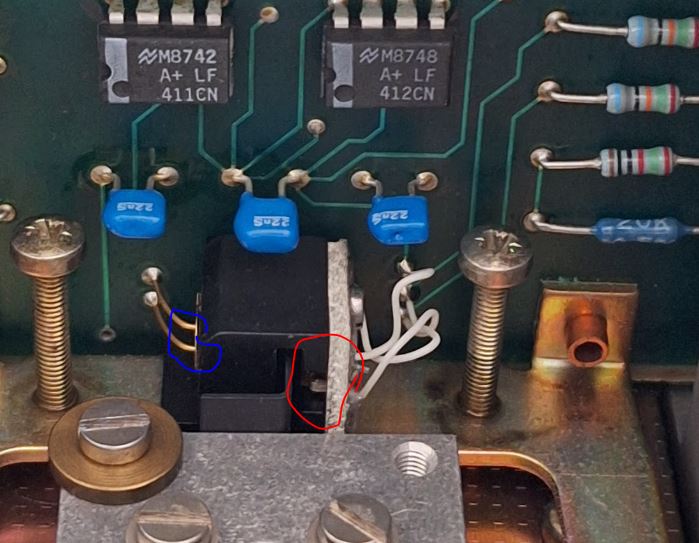
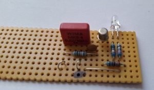
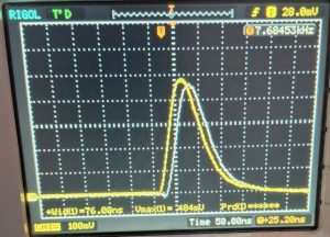
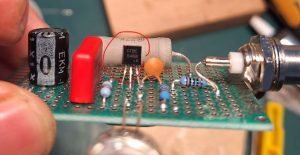
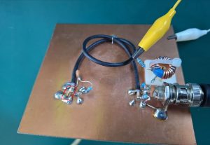
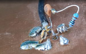
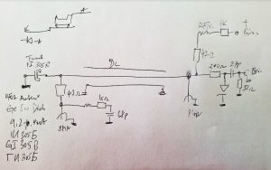
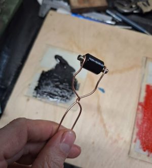
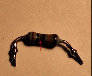
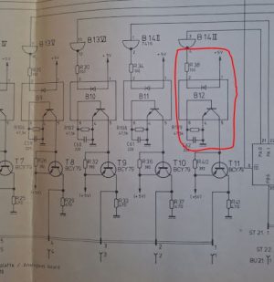
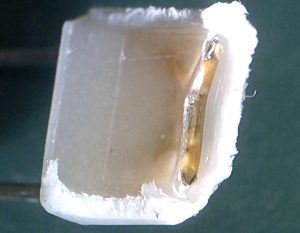
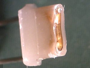
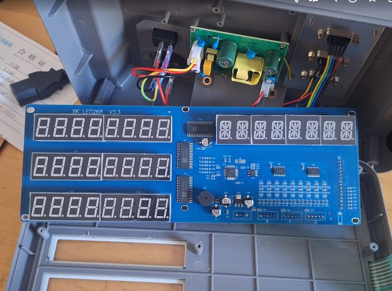
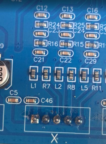
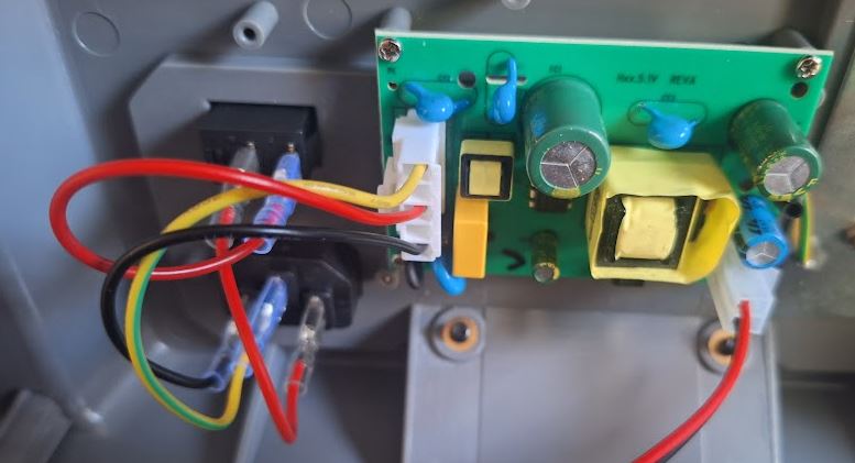
The signal first passes through some low pass filter and protection circuit: a 10 k resistor, and inductor, a R-C filter and current limiting resistors.
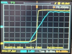
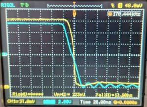
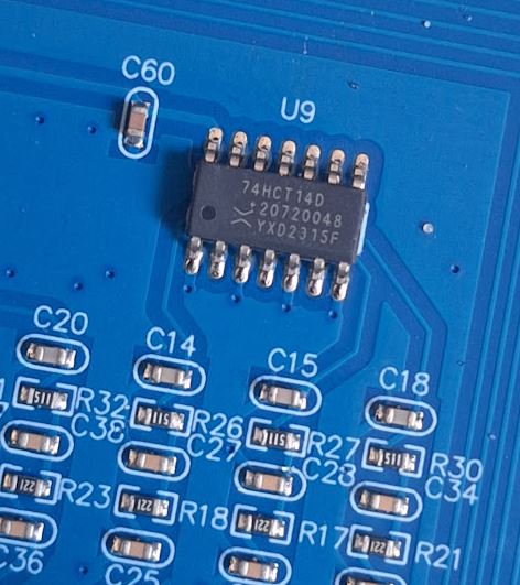
The filtered signal is further conditioned by a 74HCT14 Schmitt trigger to clean up the edges. I use the same chip for my own DRO signal conditioning, a good and cheap choice. Furthermore, these are just common SOIC parts, easy to fix (rather than some trigger input of a programmed microcontroller).
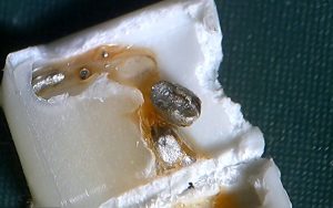
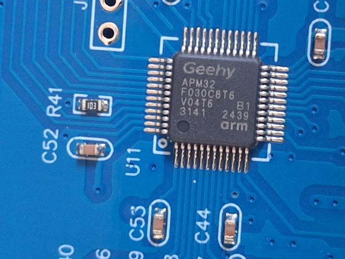
The processor is an ARM32 type, ARM Cortex-M0+ core 32-bit microcontroller, quite powerful for the application.
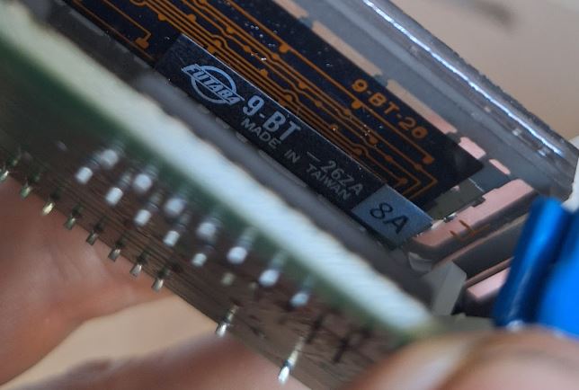
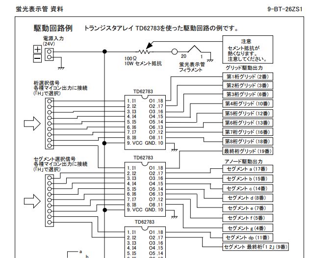
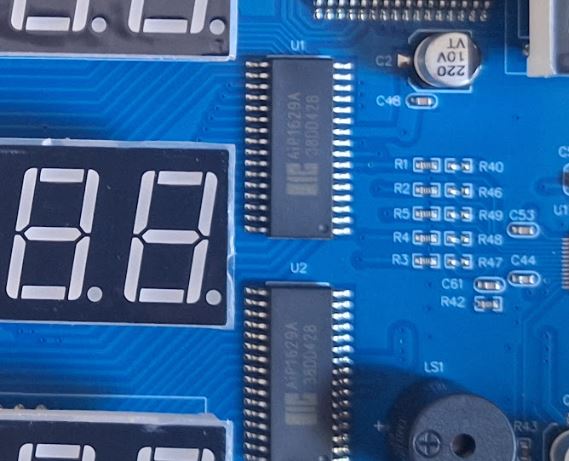
The display is driven by AiP1629A drivers, these are 16-segment 8-grid LED drivers (and keyboard scanner, but this function is not used for this DRO application).
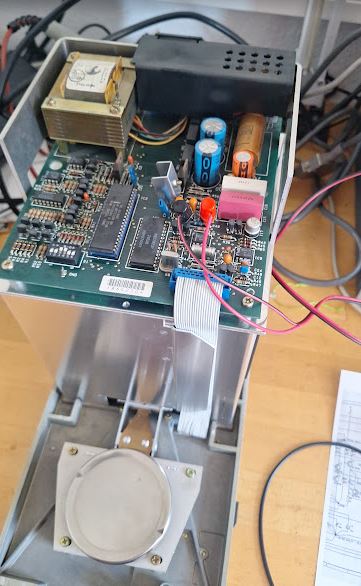
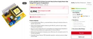
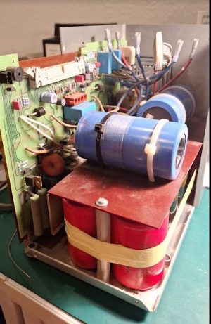
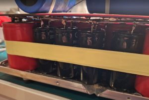
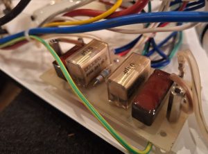
All is powered by a small switch-mode power supply, which appears to be of decent quality considering the isolation features and capacitor rating and quality level of the Y capacitors.
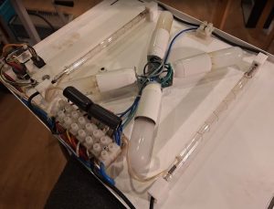
Now, for the connection to the lathe, we have do solder some wires to the junction box that currently links the DROs to a MESA Anything IO 7I92TF card.
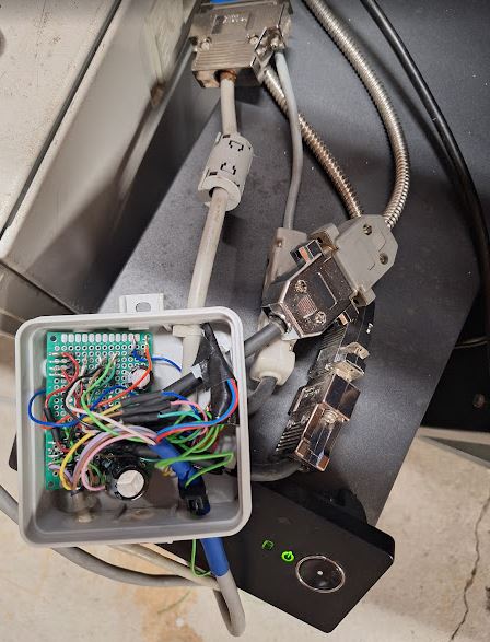
All a bit messy inside the box, but it is dust tight and has provided more than 10 years of good service in my workshop.
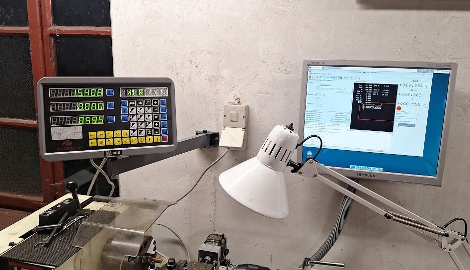
Finally, I can compare the readout the my LinuxCNC powered display (which interfaces to the MESA card via ethernet).
A few difficulties came up with the configuration of the DRO: the configuration menu cannot be accessed by pushing the A/I key or any other of the key “6 times” as often mentioned and also by instruction manual. Rather, you have to keep the “Enter” key pressed during start-up, and then scroll through the options with the arrow keys until you find the mode selection “MILL-3D” or similar, then push Enter until the desired mode shows up. By pushing the “.” key the settings are saved. For the resolution setting of the cross-slide, which uses a finer DRO, I had to use the 1 um resolution and a 250 mm/m linear compensation to get the correct reading. There are probably ways to set this differently, but it is working just fine this way. If you set up your lathe with glass scales, I highly recommend using a high-resolution scale for the cross slide, because working with diameters will half the resolution you get (10 mm travel corresponds to 20 mm diameter change!), and on a lathe, 10 um is a long distance when it comes to diameters of holes for bearings and similar.
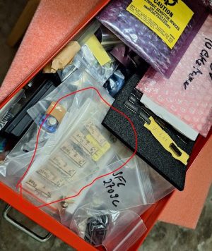
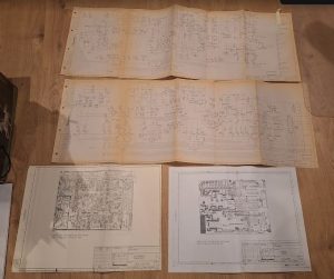
There are also a few manuals about these DROs in my collection (the paper version seems to be a little outdated, anyway, good enought). If you need any of these and can’t get them from the supplier in time, just contact by email.
Sino DRO Manual (different brand from HXX)
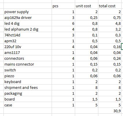
A little study of the parts cost: probably hard to have less than 30 EUR in material, even considering mass production parts cost. If you buy the parts retail, easily already 50 EUR just in parts.
There is still the holder, wall bracket, two large screws and nuts, and related hardware that may cost another 3-4 EUR. Hard to believe that such device can be made, marketed, sold, shipped and supported (by an estimated 5-10 min of customer support time) at a profit to the HXX company.
While the cheap parts and microprocessor and such cause no harm, there are two items that are a little “cheap”. Firstly, there is no filter foil for the display, and while it is bright green, the contrast in workshop lighting is not that great. Would be nice to have a green filter to improve readability. Secondly, the case is made of reasonably solid plastic, probably ABS, but some high-end DROs have cast aluminum cases that will survive in rough workshop environments better than a plastic display. For hobby use and for workshops that take care of their equipment, plastic will be good enough for a long time, certainly more durable than some of the recent touch screen DROs or DROs with fancy LCD screens that will fail after a few years of use.
All in all, very happy with the purchase, and speeding up my work. Many Thanks to the HXX company to provide such a nice instrument for an affordable price.
Note: to reset all options to factory conditions, there is password required. My unit had password “2000” when received.
Recently, I have also scanned to original paper manual that came with the unit.