HP 11683A Range Calibrator: no power meter calibration without it

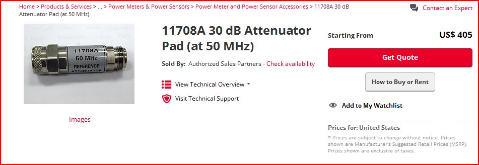
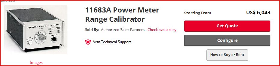
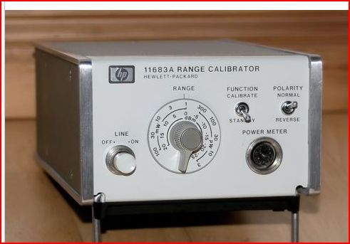
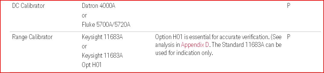
With all the various HP power meters for repair, it would be really handy to have a range calibrator, HP Agilent Keysight 11683A. These have been around for 40+ years – any still not easy to find at any reasonble price – even used and non-calibrated units may be as much as 500 to 1000 USD. You can still buy it new:

11683a range calibrator

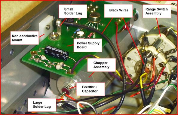
The internals, check out the picture provided by Keysight – there is a modified 8481a power head (using the same FET chopper assembly), a range switch using high quality 140 series Micro-Ohm non-inductive wire-wound resistors (0.1%, +-10 ppm temperature coefficient).

11683a internals

11683 schematic

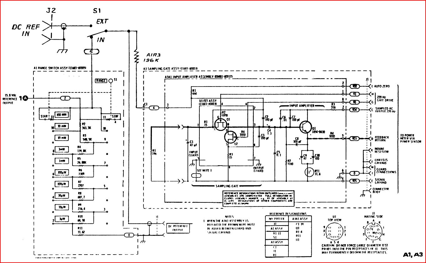
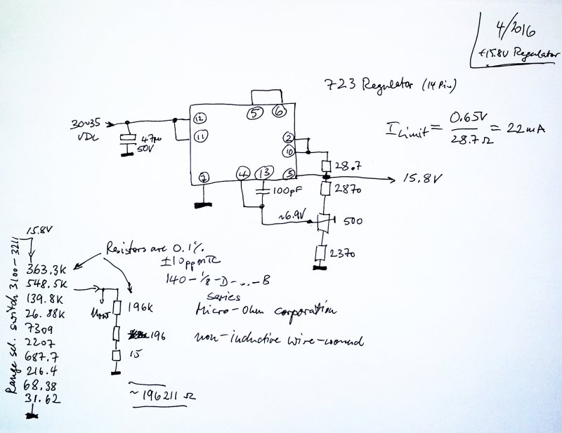
Note that the schematic shows the H01 option – which allows an external DC connection, from a calibrated DC source. This is much preferred over the build-in power supply and resistive divider (which has known issues at low output voltages). The design of the 11683a also has some ground loop issues, better to just leave it disconnected from mains, and supply the DC voltage from a known-good source.

11683a calibrator instrument

These issues are known to the experts of the field, see, e.g., this comment from the Keysight EPM-P power meter manual.

11683a accuracy

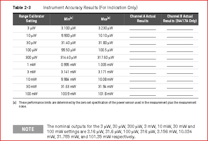
Now, a very complicated issues with the range calibrator – it’s output isn’t strictly linear over the dB range, because the power meters have a shaping circuit, to compensate for the somewhat high output of the 8481A and similar sensors, above about 5 dBm of input power. Accordingly, the sensitivity is reduced for this range.

11683a 436a pwr meter high input signal adjustment

Furthermore, the 11683a has ranges labelled in mW, e.g., 3 mW, but the output actually is calibrated in 5 dB steps…. so the output power is more like 3.16 mW, etc.
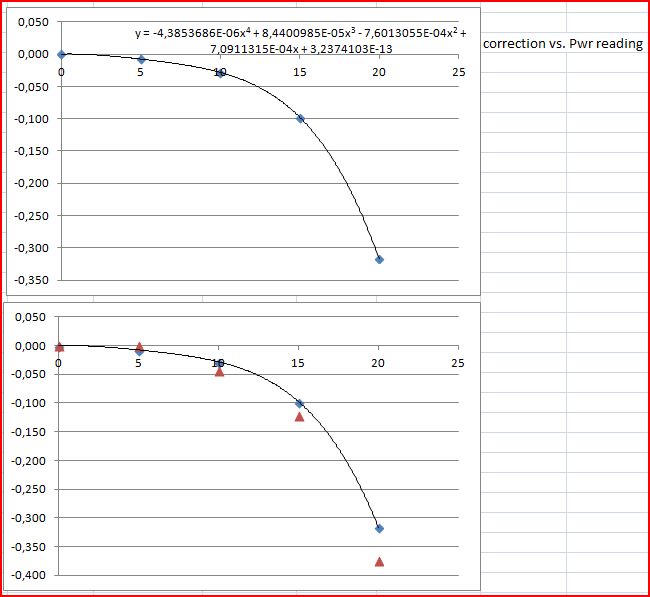
To figure this all out, a thorough calculation has been done, considering the FET input impedance, the resistive network, and the range switch.

11683 nominal output

11683 dc calibrator input

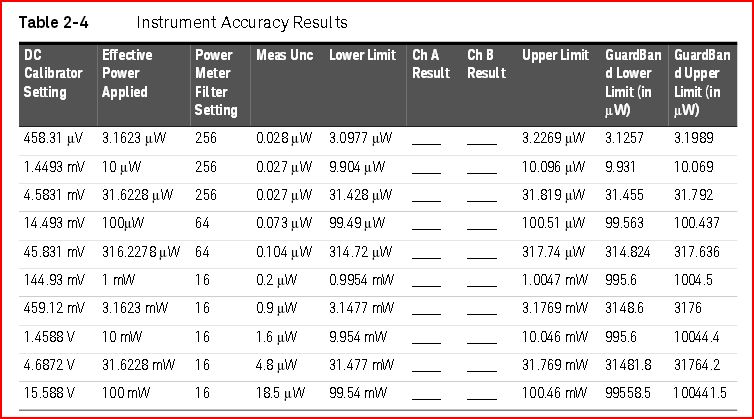
At the 10 mW and 100 mW ranges, calibrations applied in the 11683A (and the 43x series power meters) were determined to be different from the newer EPM-P meters – quite surprising. The reason for this difference of the older meters, to the new EPM-P meters is rather hard to guess, but thanks to a kind engineer at Keysight, we now know: the EPM-P meter reacts differently to the 11683A (because it measures in virtually one range), in contrast to the 43x series meters that have several ranges. So, there is no difference in the actual power meter calibration, it is just a difference needed when considering using the 11683A for either 43x or EPM-P meters, because of the different response to the level calibration, but not actually different response to the power head when measuring actual RF power.

11683 correction

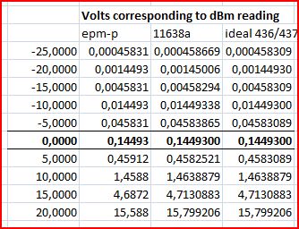
This table has the voltages that should be provided to the calibrator, depending what you want to do – (1) calibrate a EPM-P meter, (2) calibrate a meter “simulating” the acutal 11638A range switch voltages, (3) calibrate an old 43x power meter, with corresponding scaling factors for 10 mW and 100 mW ranges.

11683a ideal voltages

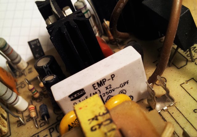
A quick scheme of the 11683A power supply, and the clear-written resistor values, which are not so clearly seen in some of the schematic copies.

11683 pwr supply

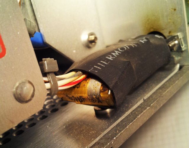
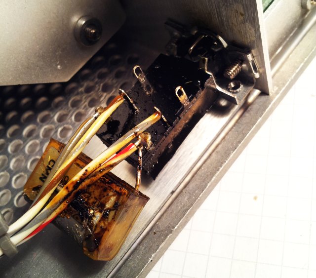
Now, how to get a 11683A range calibrator at reasonable cost? Turns out, you can build your own from one of the many defective 8481A that are around in most labs, and on xbay. Well, in fact, most “working” powerheads sold only for below USD 100 are dead anyway… but this is different story. These powerheads hardly ever have any issue with the copper and FET boards, but in most cases, the thermistor is dead, blown by too much input power.

11683 436a voltage check

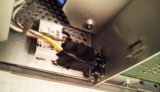
The modification – a wire has to be added to connect signal and guard ground (brown wire), and a 196 ohms resistor soldered over the FET input (I used a 220 ohm resistor for the test, but will replace one 196 ohm on hand). Also, you need to add a 196k resistor to the input, according to the 11638A schematic (this can be assembled from some other resistors, if no 196k in stock).

11683 8481a modification

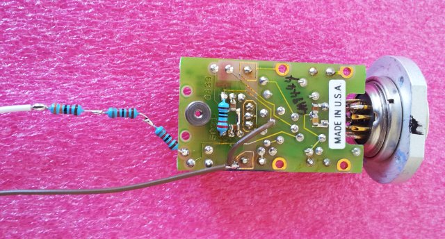
Make sure not to bend the wires – this can affect the FET chopper balance (see 8481A or 11683A service manual to re-adjust if needed).

11683 8481a board

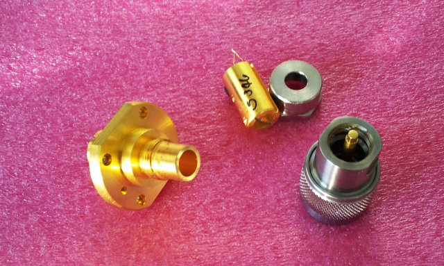
The input is currently still arranged with open wires, but I will fit a 1n feedthrough cap soon – will modify the original N-connector (the golden part holding it). But this will need to be done back at the main workshop in Germany – need to use a lathe for it.

8481a n conx disassembled

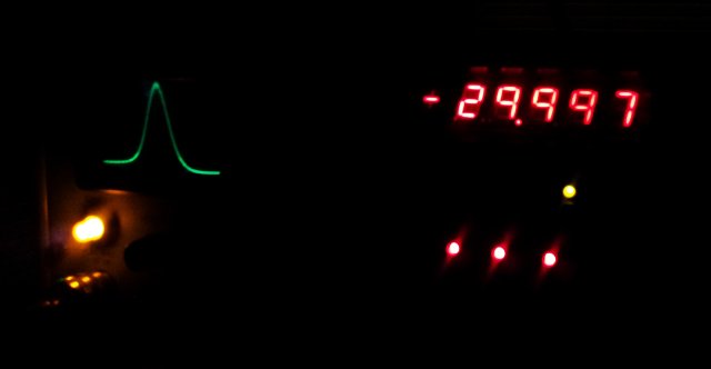
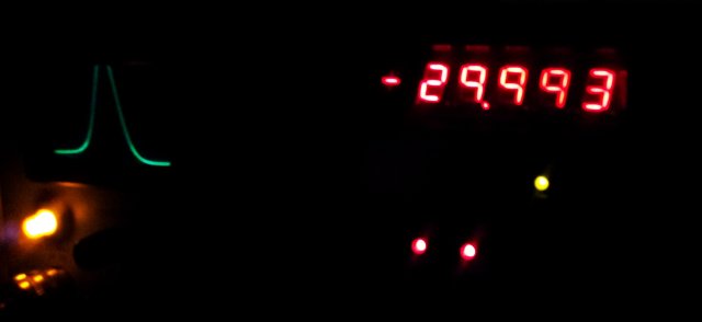
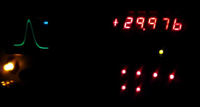
Some test results will follow soon – but so far, everything is working just fine.

HP 11708A 30 dB Reference Attenuator: less than 0.0005 dB drift per year?

One of the products that have been in the HP/Agilent/Keysight catalog for 3 or 4 decades, or more, the 11708A reference attenuator. Specified at +-0.05 dB, it is a remarkably simple device – it just provides 1:1000 attenuation, chiefly, 30 dB. It’s main application is the calibration of 8484A power sensors, from a 1 mW source – the 8484A needs a 1 µW reference level.

Unfortunately, it doesn’t come cheap, when ordered from Keysight today, at least for a hobbyist’s budget. So I got mine used, aged (30 years?), and at a minor fraction of the cost.

11708a keysight

Before using it for a considerable number of power measurements, it is a good idea to confirm it’s performance. Measuring attenuation to +-0.05 or better is no easy tasks, but fortunately enough, a tractable one, with a 8642A signal generator, and a Micro-Tel 1295 precision attenuation measurement receiver. The Micro-Tel is specified to +-0.02 dB, plus +-0.02 dB for each 10 dB, say, +-0.08 dB. Actual performance, of a well-calibrated and well-heated-up unit is considerably better, but only in combination of other high quality components, like, a stable source (the 8642A has virtually no measurable drift), and, good test cables (using Suhner Sucoflex).

The Micro-Tel 1295 employs IF substitution to determine attenuation, and the IF attenuator works in 10 dB steps. Therefore, for best accuracy, the tests should be done at various power levels, to use various combinations of x0 dB segments, of the IF attenuator.

The results, quite remarkable!

11708a low level

11708a low level2

11708a high level2

One thing to consider for the test – the input and output matching losses. Neiter the source nor the cable/receiver are perfect 50 Ohm terminations – but the 6 dB pads will ensure only very minor losses. Obviously, you need to use high quality pads here, specified to small return loss, 18 GHz parts preferred.

First step – reference measurement is taken without the attenuator-under-test:

11708a test atten 1

Second step – actual measurement is taken with the attenuator-under-test installed between the two 6 dB pads:

11708a test atten 2

Before the start – best to check reproducibility and repeatability. With good cables and hardware, +-0.005 to +0.01 is achievable with the current setup.

Well, let’s say, chances are that the 11708A is +-0.02 off its nominal value, most likely, it didn’t drift at all over the last 30 years.

TIC4 Time Interval Counter: 64 bit timestamps – 100 ns resolution

A time interval counter – this little device, based on an Atmel AVR ATMega32L assigns 64 bit time-stamps to events (event being a rising edge on INT1 interrupt), based on a 10 MHz OCXO, a Trimble 65256 10 MHz double oven oscillator. So, 100 ns resolution. The main purpose: precise monitoring of pendulum clocks – in combination with a temperature-air pressure-real time clock data logger.

Why TIC4 – well, there are several other (earlier designs), some with better resultion by interpolation (via a clock synchronizer and interpolation circuit). But for the given purpose, there is no need for any more than a few microseconds of resolution, because it is really hard to detect the zero-crossing of a mechnical pendulum to any better resolution.

For test purposes, I had the circuit running on a 16 MHz clock, with ordinary (not very precise or phase locked) 20 Hz, and 2 Hz signals at the input – running overnight to check for any glitches.

tic4 allan dev 50 ms

tic4 allan dev 500 ms

The Allen deviation plots show that for single events, the timing accuracy is about 150-200 ns, close to what is theoretically possible for a 16 MHz clock.

The AVR program code, it looks simple, but believe me, it isn’t. There are quite a few pitfalls, because for any timing of the interrupt, there needs to be a precise time-stamp generated, and transmitted to the host. Maximum time stamp rate is 100 Hz nominal (1 timestamp every 10 ms), but will work up to about 150 Hz, without missing any events. Timestamps are transmitted with every 16 bit timer overflow, chiefly, every about 6.6 ms (65535 x 100ns). Each timestamp and control info is 120 bit long (12 bytes, 8N1 protocol, 57600 baud) – 2.1 ms.

tic4.c AVR code

For test purposes, the serial data is sent to a PC, via a MAX3232 TTL to RS232 converter. Alavar is used to process the information into Allan deviation plots.
Test showed absolutely no glitch in about 1.3 million events – fair enough!

More details to follow.

Ordinary Wheat Bread: well-proven US recipe

This is a good, fast and simple wheat bread. Optimized for baking in gas-fired ovens.

1600 g wheat flour (1:1 mix of ordinary and bread flour; up to about 300 g wholewheat flour is OK)
30 g salt
1 package dry yeast

Dry-mix thoroughly.

Add 1200 mL of warm water.

Mix/knead. Let rise thoroughly. Knead again – add some flour as needed.

Form elongated shape breads. Let rise.

Bake in pre-heated oven to 425 F. For best result, add water in tray at start of baking.

ordinary wheat bread

Some (good old German) baking recipes: strudel, marble cake, Gugelhupf

Gugelhupf

500 g Weizenmehl Type 405
1 Msp. Salz
1 Würfel Hefe
150 g Butter
100 g Zucker
3 Eier
225 mL Milch

Hefeteig zubereiten. Gehen lassen.

100 g Rosinen (abbrühen und durchsehen – schlechte aussortieren) unterkneten.

In Gugelhupfform geben, gehen lassen

180 Grad Unter-/Oberhitze, 50 min backen – etwas in Form auskühlen lassen, dann stürzen. Puderzucker aufbringen wenn kalt. Fertig!!

gugelhupf

Marmorkuchen

250 g Butter
260 g Zucker
6 Eier
1 Msp. Salz
Gründlich schaumig schlagen.
400 g Mehl mit 1 Pck. Backpulver mischen und durchsieben.
170 mL Milch

Rührteig zubereiten.

Hälfte davon in Gugelhupfform.

Zum Rest: 100 g geriebene Bitterschokolade und 40 g Kakao. Gründlich durchrühren.
In die Form geben und mit Messer durchmischen (marmorieren)

Backen: 160 Grad Umluft, 50-55 Minuten (mit Holzstab prüfen)
In Form etwas abkühlen lassen, dann stürzen. Puderzucker drauf oder Glasur (nach Geschmack). Fertig!!

Strudel (Quark- und/oder Kirsch)

Strudelteig zubereiten aus
500 g Weizenmehl Type 405
1 TL Salz
1/4 L lauwarmes Wasser
80 g geschmackloses Öl (Sonnenblume, Raps)

30-60 Minuten ruhen lassen!!

Füllung:
500 g Magerquark
200 g 40% Fett Quark
4 Eier
120 g Zucker
40 g Gries
Alles gut mit Schneebesen durchrühren.

150 g Mandeln gemahlen (auf Füllmasse aufbringen)
1 Glas Kirschen (gründlich abtropfen, für Kirschstrudel), oder 200 g Rosinen (gut wässern und aussortieren), fuer Quarkstrudel

Zweckmässig 3 Strudel formen auf bekannte Art (Teig dünn ausziehen, Quarkmasse aufbringen, gemahlene Mandeln aufbringen, Kirschen oder Rosinen aufbringen, Strudel zusammenrollen)

100 g geschmolzene Butter – Form gut ausstreichen, Strudel gut streichen.

Evtl. Vanillesauce dazu.

175 Grad Umluft, 45 Minuten backen. Fertig!!

strudel

quarkstrudel

kirschstrudel

HP 436A Power Meter: smoke and stench – X-rated cap failure

By coincidence, another HP 436A power meter – this one, emitting smoke and terrible stench! The culprit was easily found, a defective X-rated cap. One of the known-bad epoxy covered capacitors that tend to blow after about 30 or 40 years of service.

436a x2 capacitor 100 n

The residue, oily stuff, terrible smell. Use plenty isopropanol or methylated spirits to clean – otherwise, the stench will stay with the instrument for years, and I can’t say that it is a healthy smell.

436a 100n oily

The cap is of the well-known PME271M series. Still available, but hopefully, with improved construction.

436a pme 271 m 610

436a pme271 series

A replacement is easily found – taken from an old switchmode power supply. Make sure to take a “X2” cap, not an ordinary cap. Only X2 caps are specified for mains voltage service, and self-exinguishing, anything else will present a major fire hazard, don’t compromise on the choice of capacitor!

436a 100n x2 replacement

Fix complete – new cap soldered in, and insulated with some electrical tape. In general, I tend to avoid electrical tape where possible, but in this case, it appears to be the only viable solution.

436a fix complete