TWS-N15 Noise Source: noise generating elements

Some trials with various low-cost noise generating circuit elements:

(1) Zener diodes
(2) Transistors B-E junctions in break-down mode
(3) Noise diodes – these are not being considered, not low cost.

For (1), a BZV55-12 diode was used, directly soldered on the traces of the noise source circuit described earlier.
For (2), as a first try, a BC238B transistor was used (with legs cut to very short length). Sure, I will try some RF transistors, but these are all back in the main workshop in Germany and will come over in a couple of weeks.

noise bc238b lin

noise bc238b log

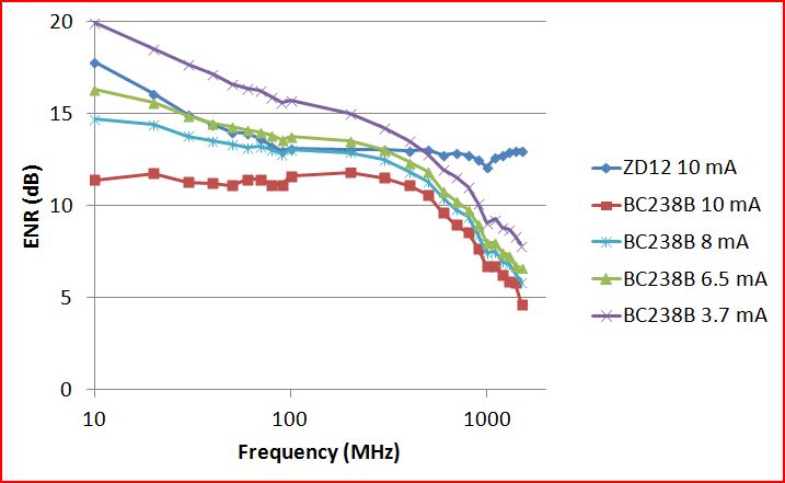
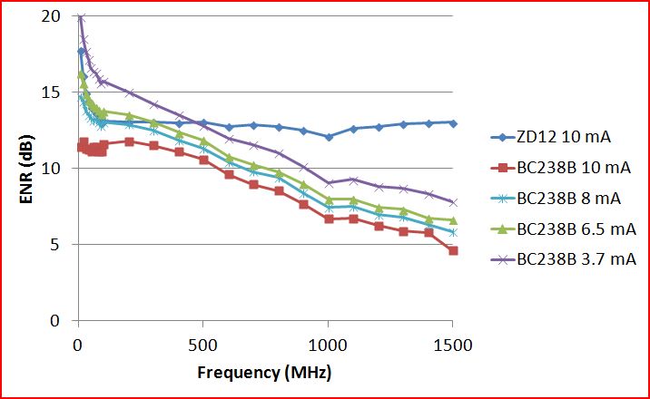
The output, measured with a HP 8970A noise figure meter and some GPIB software to do this efficiently, it shows quite interesting behavior.

For the Zener diode, there is appreciable 1/f (pink) noise at <30 MHz, but the output is pretty much flat at higher frequencies. The transistor, well, it is working fine at lower frequencies, at 10 mA bias, the noise is flat-white up to about 300 MHz. But not enough noise at higher frequencies - maybe just not the right part for this purpose. These are just a few of the components tested, stay tuned.

TWS-N15 General Purpose Noise Source: some progress on the design, and some tests

Many design of amateur noise sources have been published, they all have there benefits and shortcomings, but it is mostly the lack of a calibrated test source that makes it difficult for the hobbyist to employ a cheap, home-made noise source for the ever-so-critical noise figure measurements of the amplifiers and mixers he may build.
Having recently acquired a good calibrated source, HP 346B, I have decided to make available a noise source design and build so many, and calibrate them, in order to make calibrated sources, up to, say 1.5 or 2 GHz, available for everyone at a really low price. Thinking about USD 45 per piece which should be fine for everyone dealing with such measurements.
Requirements are pretty simple, it should be a ‘low-frequency’ replacement of the HP 346B, about 15 dB ENR output, flatness, preferably, within 0.5 dB, starting from 10 MHz. It should also have high output return loss (low SWR), which can’t change significantly from on to off state. Last but not least, powered by the ubiquitous 28 VDC noise source drive signal common to most noise figure analyzers.

The bill of materials, combined with the desired target price, won’t allow the use of a custom-made noise diode. But this is not really a disadvantage for the intended frequency range and purpose.

Three main tasks will have to be solved, to get this thing (called, the TWS-N15 Noise Source) to work:

(1) First and foremost, we need a noise generator circuit; these require a bias current, typically 5-15 mA.

(2) We need a temperature-compensated current source; currently experimenting with discrete Zener and TL431 based circuits. Current should not vary significantly, if input voltage is changing from, say, 27.5 to 28.5 VDC.

(3) Mechanical package. This is quite important, because the noise source needs to be well shielded, and put in a sturdy case – these sources tend to float around labs, and are often dropped, or dragged down from the bench by the heavy cables attached. Output connector will be SMA, because I have a large supply of really nice quality SMA print connectors.

The draft schematic (current source not shown, cirucit works, but still need better characterization, and possibly, some improvement). Note that the output attenuator will set the ENR level. Might need to adjust this a bit; for the time being, anything from 10 to 15 dB ENR will be fine.
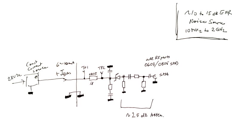
tws noise source schematic

This is the small cirucit, build on a 0.6 mm FR4 board. Traces were simply carved out with a knive…..

2 ghz noise source

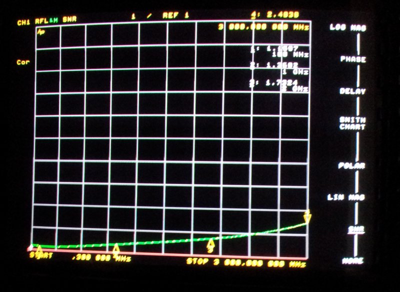
Here a few plots from the VNA characterization. Not bad for a start. Input return loss is at least 15 dB. This will still be improved. Using 0603 SMD resistors for the critical section.
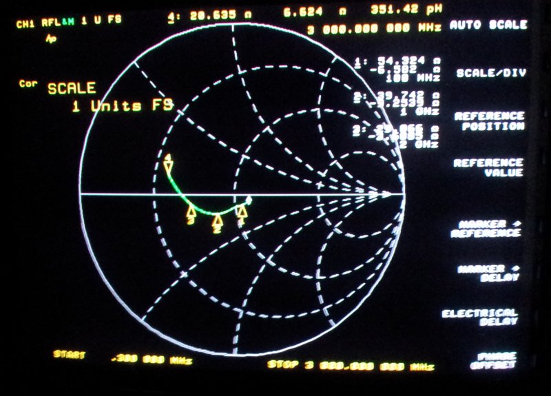
tws noise smith chart

ON and OFF traces are shown – virtually, no effect on the return loss.
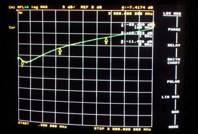
tws noise rfl loss on off

tws noise swr

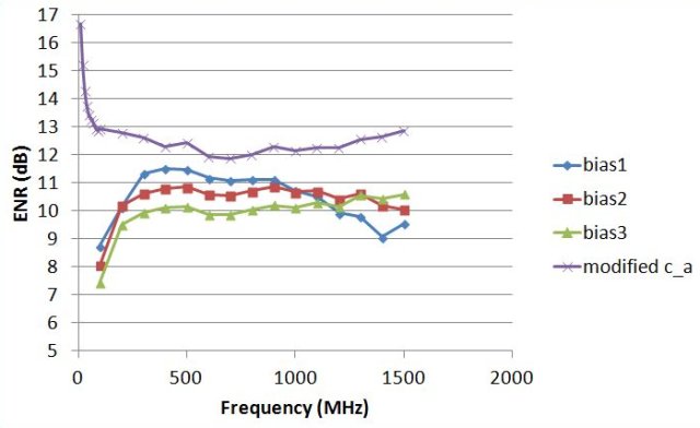
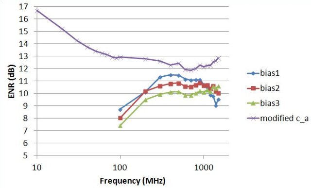
Some tests of the noise output, really much better than I thought. Bias current has some impact on flatness; low frequency end is determined by the first capacitor (between diode and attenuator). This will need some further tweaking to get it as flat as possible, but no rocket science.
To measure the noise output flatness and level quickly, there is no also an automated test rig here, which measures bias current and on-off noise figure differences.
noise source test1

noise source test1 log

Next steps… will need to decide if the 0.6 mm board is the best option (these boards allow rather narrow 50 Ohm traces; most of them, I machine using a router mill – no etched traces), or if a commercially made board of regular dimensions would be the better option. Cost ist not really a concern, because the noise source only needs little space. Stay tuned.

HP 8565A Spectrum Analyzer: a ‘new’ CRT for a trusty unit

Not a very major repair, but certainly, noteworthy. I have a 8565A here on the bench, and actually use it quite a lot, along with the 8569B, because it saves you a lot of time not to have to wonder about all the buttons and switches of more sophisticated analyzers. Also, for its coverage (up to 22 GHz with no external mixers), it is rather affordable, and should it suffer from accidental abuse, which can always happen on a test bench with so many cables, it is rather easy to fix because of parts units being available, and because of its discrete construction. Needless to mention, full schematics are available from the HP service manuals.
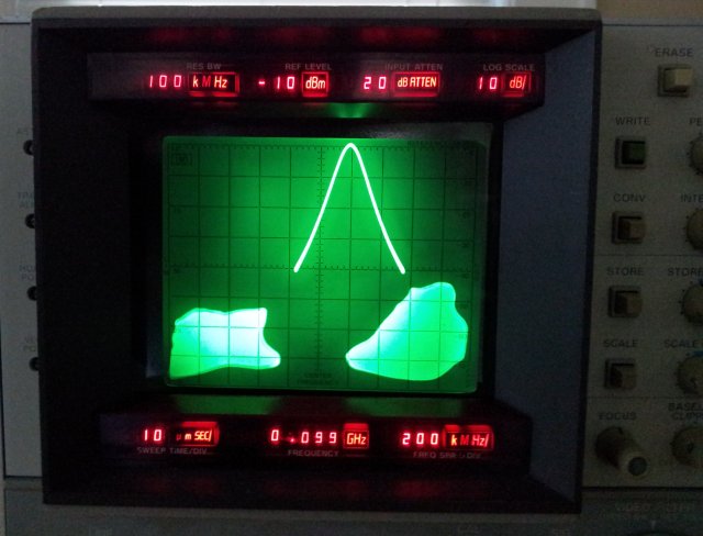
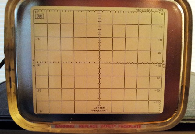
The only downside of the unit, the CRT – it is working just fine, for all practical purposes, but has some ‘slow’ sections in the variable persistance and storage modes. These show up as green spots in the baseline region. Over time, you can make them disappear, but it takes multiple erase cycles, quite a tedious procedure. For the most part, I just did not care about these spots.

8565a old crt

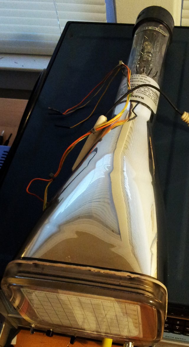
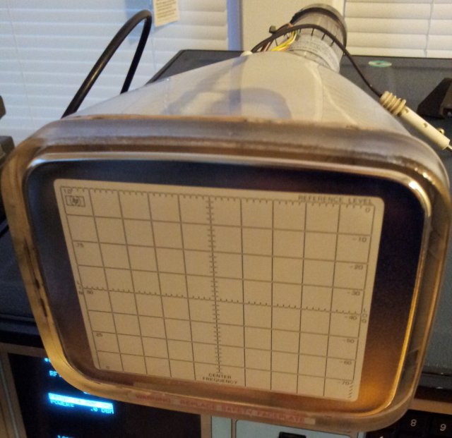
Fortunately enough, I was able to get hold of a spare 5083-4471 CRT, which has been sitting in the storage room for quite a while. Condition was said to be ‘essentially new’ but never checked.

crt 5083-4471

8565a crt screen

8565a new crt

Last week, finally decided to give it a try, risking to have to install the old CRT again, in case the new one doesn’t turn out to be so new.

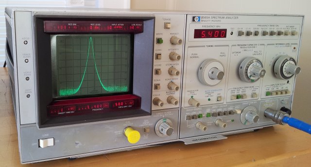
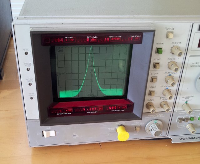
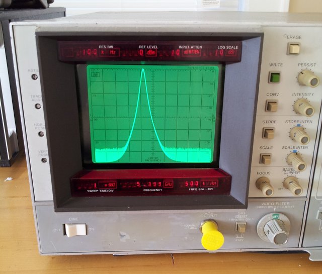
You be the judge…. conventional mode

8565a crt conventional mode

… stored display …

8565a new crt storage

… variable persistence mode …

8565a new crt variable persistence

…. good as new.

Clothes dryer repair: AKO 742336 control unit type EDR0692XAX

Repairs of household appliances aren’t generally my field of expertise, but in some cases, it can be a very rewarding activity. Some particular models of clothes dryers (“AEG”, “Whirlpool”) common in Europe use a control board, and this is not designed up to standard. The design flaw, it renders the machine inoperative in the very sense, you can’t switch it on, and it doesn’t show anything on the display. Typically, this occurs after roughly 3 years of service….

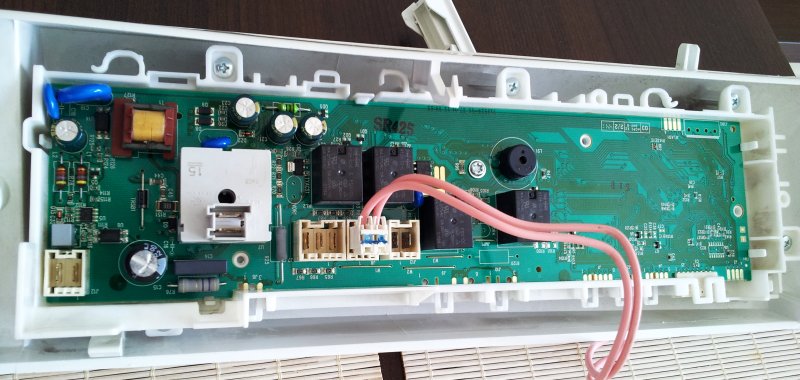
This is the control unit:
dryer control

dryer control board

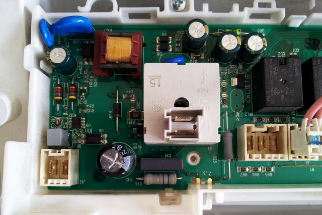
dryer control board detail

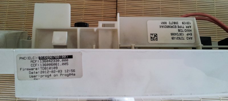
edr0692xax board

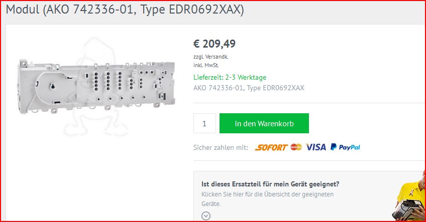
After a quick inspection, it is fully clear that the defect rests with the control board, model EDR0692XAX. Easy fix, just get a spare! Well, easy, but outrageously expensive.

ako 742336 edr0692xax

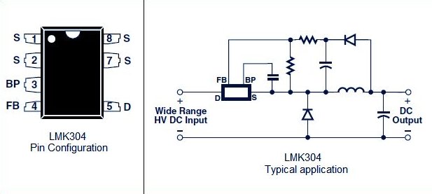
The defect, it is related to a DC switch mode regulator converting mains voltage down to some useful voltage to run the controller. This is a step-down converter, NOT mains insulated!

lmk304 application

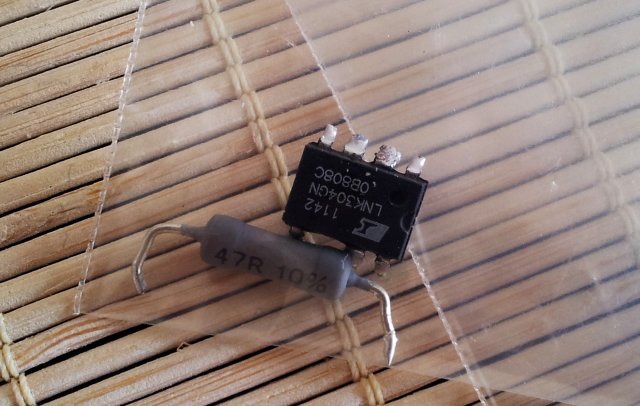
Two dead parts were found, the LNK304 switch mode converter circuit, and a 47 Ohms resistor.

dryer control lnk304gn 47r resistor

The LNK304GN is easily found, and replaced. The resistor: WATCH OUT! This is a fusible resistor, NEVER replace with just a common resistor – it will potentially set your house on fire, when the next switch mode failure happens.
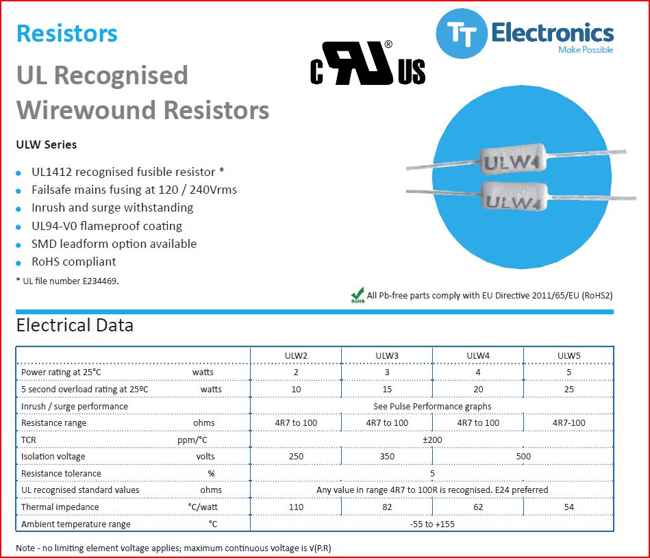
The 47 Ohm resistor, it’s a 3 Watt resistor, and the ULW3 series, available from all major suppliers, should be a good replacement.

ulw3 fusible resistor

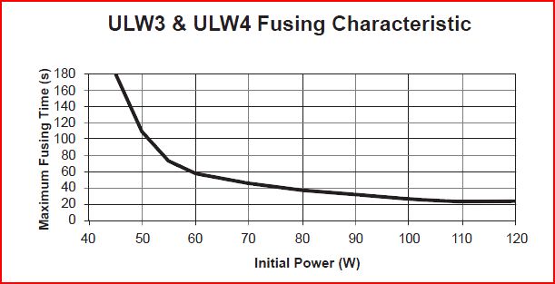
This is the failure charcteristics of the ULW3 resistors – it will go open circuit if overloaded, without release of any flames or particles. It a hybrid, partly fuse, partly resistor.

ulw3 fusing characteristics