3047A Phase Noise Test Set: getting closer…

Quick update on the 3047A software:

(1) Implemented the beat note search for low frequencies – using the 3562A analyzer. This is now working just great, using a zero crossings algorithm.

(2) Implemented the loop correction (including the “Difcorrection” method).

(3) Implemented the phase detector slope measurement for low frequencies – using the 3562A analyzer.

(4) Implemented loop characterization for below 20 Hz. This utilizes the noise source of the 3562A, and both channels, to measure the transfer function. Actually, sounds easy, but took quite some effort to get it to work properly.

That’s the latest version of the source.
main – 150329 backup

A quick test with the 8782B – and, it seems to work!
8782B PN test loop corr

Will put it to a test with a very narrowband PLL soon.

HP 3047A Phase Noise Measurement: progress on the low frequency part, and a GTK interface.

Quite some progress on the 3047A software – while I don’t really need a lot of phase noise data below a few kHz, still good to have things complete and working. As mentioned earlier, the 3047A test system used the 3582A FFT analyzer – which is very much outdated, apart from the fact that I don’t have one around. So a little bit of adaption, to incorporate a 3562a into the system.

To test the setup, three generators were tested, vs. a 8662A reference:

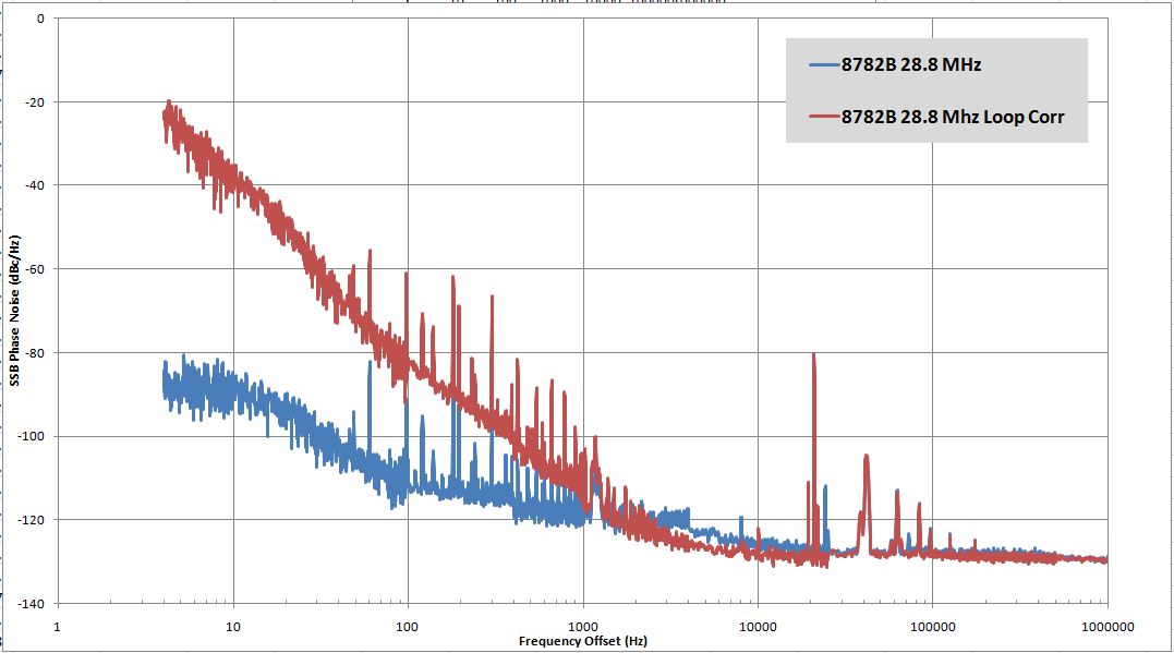
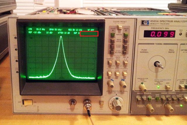
A 8782B at 28.800000 MHz (ref: 8662A DC FM, 5 kHz/V, scope: 50 mV/div):
pn 8782 50 mv per div

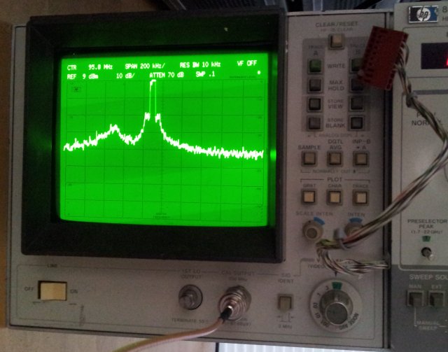
A 8782B at 28.800013 MHz (ref: 8662A DC FM, 5 kHz/V, scope: 50 mV/div):
pn 8782 50 mv per div at 28800013
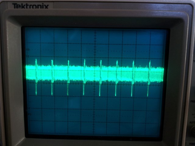
Note the spurious content, seems to be related to a fractional divider in the 8782B.

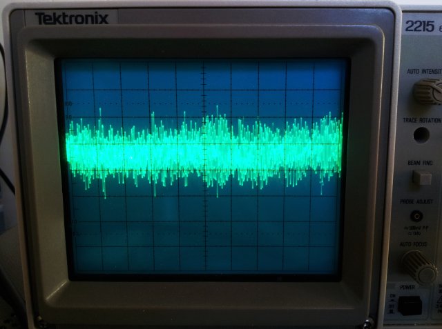
A Micro-Tel SG 811, which is a free-running generator (ref: 8662A DC FM, 100 kHz/V, scope: 1 V/div):
pn mtl 1 v per div

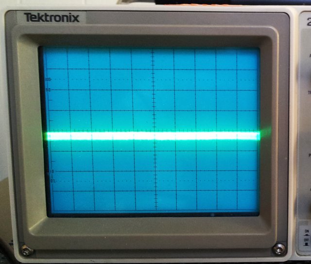
And, as the “gold standard”, a 8645A (no picture, scope shows just a flat line, with a few mVpp).

pn test

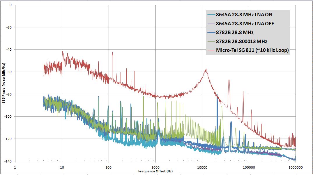
A few items – firstly, the 40 dB LNA of the 35601A interface is working fine – see the tests with and without – very little offset, except in the 1 kHz region, where such offset can be expected due to noise levels/parasitic noise of the setup that can only be overcome when using the LNA. Secondly, see the sharp drop at just above 10 kHz for the Micro-Tel measurement – this is corresponding to the loop bandwidth of the PLL. Note that the lower frequency data were only collected for test purposes – they are within the loop bandwidth and more or less invalid at below 10 kHz for the Micro-Tel, and below ~1 kHz for the others.
Above a few kHz, the system reaches the noise level of the 8662A – except for the spurs, and the Micro-Tel.

Afterwards, a quick reproducibility check:

pn reproducibility

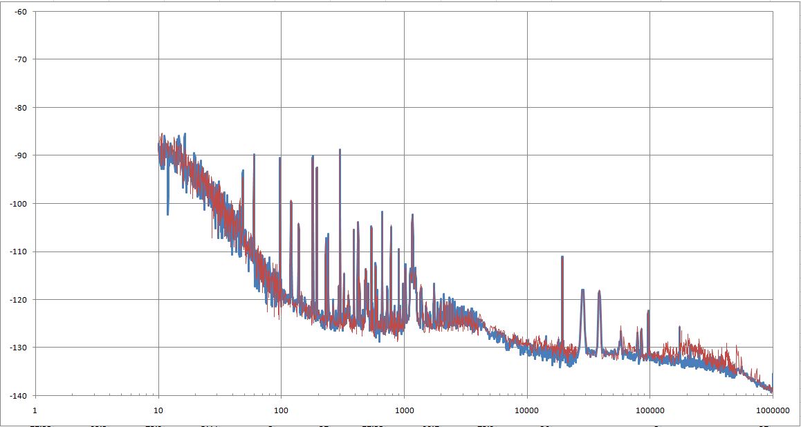
The transition from the 3562A to the 3585A analyzers occurs at 25 kHz – sometimes, there is a little step. Need to check this further – maybe related to the disabled auto-recalibration of the 3562A.

Remaining items:

(1) Beatnote measurement for low frequency, using the 3562A – this is needed to test using very narrow bandwidth PLLs, like with voltage control inputs (ECF) of stable crystal oscillators.

(2) Phase slope measurements for small offsets, using the 3562A – currently, using the DC FM tuning input of the 8662A with a few kHz deviation – but this extension is needed for narrow loop BW/small tuning range as well.

(3) Some general cleanup of the code, and full incorporation of the PLL loop suppression correction (section “Difcorrection”). Nevertheless, that’s the current status, with some bugs fixed over the earlier version (LF filter settings F0, F1, F2, and some other minor things).
pnt_ main _150322

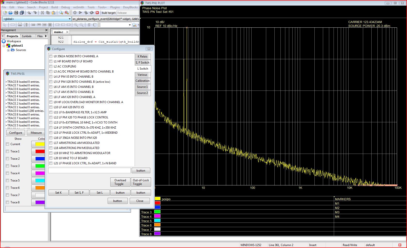
(4) Finally, adding some user-friendliness. Quite a bit of progress on this front, with a GTK based interface (need to implement the hardware control layer). Here a first glimpse.
tws pn1 gtk

HP 8569B Spectrum Analyzer: almost the same, not quite identical

It took the best part of two hours to find the reason for the mixed mode malfunction-the lacking sweep time denominator issue. By comparison of all 84 lines going from the main front panel assy no. 08565-60002 to the analyzer, found an issue with the J1-43 line, MNL SWP (manual sweep).

8565a j1-19 man swp8569b j1-43 mnl swp

Above, old version (08565-60002 A-1645-45), below new version (08565-60002 B-2430-53).

8565a old board
8565a new board

8565a front switch assy modified

8565a wire

No big deal, added a yellow wire, to connect the pushbutton contact to the J1-43 line.

8569b working

A quick test, and it is working just fine!

Now, the only thing remaining are the knobs, but this will have to wait a few more weeks.

H 8569B Spectrum Analyzer: some progress, and a few more items to fix

A brief summary of the somewhat tedious job of fixing the 8569B front controls, which are a great feat of engineering but the plastics are prone to aging:

First, replacing the gear, it is a 48-pitch, 48-tooth spur gear, glad that I had one spare, but they are still available:
8565a gear
8569b gear

Next step, some contact cleaning, using a soft eraser, and some isopropanol.
8569b cleaning contacts

The frequency control – for some reason, there are different versions around, one that has wires attached, and one the has pins – interestingly enough, the 8565a control fitted has wires, but the 8569b requires pins – also here, good to have a spare assembly around, with the pins…
8569b frequency control

Defective bias pot – also here, a spare fitted.
8569b bias pot

Some of the contact fingers broken off-also there were fixed, and everything put back together.
8569b back together

Finally, noticed that the 10 dB segment of the 70 dB input attenuator (5086-7365) is stuck. Nothing dramatic, just one of the little O-rings holding the contact actuators broken off, and parts of it stuck in the contact.
8569b 5086-7365

Finally, a quick test – everything seems to be working-
8569b display

-unfortunatly, still missing something – the sweep time indicator is not showing a time denominator (µs, ms, sec), and the analyzer remains in the digital mode for all sweep time settings – it should switch to mixed analog-digital mode (at the time the 8569b was designed, there was no easy way to run analog-to-digital converters any faster than a few kHz without causing exorbitant cost, so the 8569b uses the digital storage mode only at the slower sweeps).
8569b display missing

Remaining items:

(1) Identify the issue with the sweep time indicator and missing transition to mixed analog-digital mode. Maybe related to the 8565a control fitted to a 8569b? – Checked by substituting a control assy from a good 8565a – working just fine with the 8569b – accordingly, this is not the reason for the fault. There seems to be a defect on the main front panel board. Maybe a bad switch contact, or a broken trace. Will be quite a pain to test will all the cables, switches and screws.

(2) Manufacture the control knobs for the frequency-bandwidth-span-atten-ref level setting. These were missing and don’t have spares at hand/these wheels are getting brittle anyway. Will make a new set from aluminum alloy, during next stay, in Germany, the only place with access to adequate machine tools.

HP 8569B Spectrum Analyzer: working essentials

After two very busy weeks, finally, a chance to have a look at the 8569B analyzer (with the 8565A control). No display, no way to find out if at least the essential items are working – these include the input mixers, the YIG filter and oscillator, and other GHz frequency components.
First tests showed that the power supplys are all working and well adjusted; still no display.

Connected a scope to the rear panel output – sweep is working!

Some little repairs of the CRT section (nothing really interesting to write about) – look at this sight:

8569b working crt

Really great, a bright CRT, and well-focused. And, it is actually showing a signal – basically, a working unit. At least, a start. Now we just have to see how to get the controls fixed.

HP 8565A?? HP 8569B?? Spectrum Analyzer: a mixed box

For next to nothing, I got hold of a HP (Agilent, now: Keysight) 8565A 8569B mixed analyzer:

8569b front panel 2

8569b panel

As you can see, the main unit, including the CRT and electronics, is a 8569B, but someone fitted a (rather incomplete) 8565A control assembly. Not a big deal, normally, but the control assembly fitted here has virtually all the common defects: missing contact wipers, and missing/defective knobs.

Another common defect (can all be fixed):
8569b wheel

A quick test – the CRT seems to be working, albeit, it is now dark after a few minutes of operation – most likely, just a dead capacitor, but the CRT itself is definitely pretty good. Also the CPU seems to work just fine.

8569b yig

The unit has a lot of RF goodies, like a 22 GHz 3-stage YIG filter, a YIG oscillator, a 22 GHz mixer, various 22 Ghz coaxial relais – but with another parts unit already at hand, this unit seems to be to precious to scrap. Well, need to think about it, always wanted to provide an electronic replacement for the aging 8565A 8569A/B control assemblies. Maybe, a good project for next winter!