The 1295 receiver – before working on the internals, the external parts – the panels – needed a makeover.
(1) Sticky paint removed from side panels, top and bottom panels, using methylated sprits. Imaging scraping off dark green chewing gum, several square feet covered with it. Hope the company that sold this paint is now out of business, that’s what they deserve.
(2) Some more cleaning and sanding, with 400 grit paper.
(3) Primed with self-etching automotive primer. For coating aluminum metal, always use a suitable primer – don’t trust any suggestions on paint cans that it will work without a primer. It won’t.
After some drying, a quick sanding. Not aiming for perfection.
(4) Top coat with a modified alkyd resin. “Hunters green” appears close to the original color shade.
(5) After several hours air-drying, burn-in at about 165 °C, for 60 minutes. This improved adhesion, at least based on my past experience, and no need to wait for days before the instrument can be re-assembled.
(6) Clean the newly painted surfaces with isopropylic alcohol, this gives an even shine, and to confirm that the new paint is fully resistant vs such solvents.
(7) Re-assemble all the small hardware and screws, feets, etc, of the panels!
The other items:
(1) Added filter caps to the YIG driver, when under remote control (more or less a bug in the Micro-Tel circuit).
(2) Added a parallel ot serial converter to the display – the readout values are now transmitted via 2400 baud, via the external control connector. See post in the attenuation measurement section. The circuit involves an ATmega32L which monitors the display for an update, and with every update occurring, it reads out the value, and does the transmission – no handshake.
(3) All frequency related and AFC adjustments, YIG driver adjustments etc. have been performed. Calibration of attenuation levels checked – seems OK – precise calibration, I can only do back in Germany. But seems to be in-spec, and will compare more throughly vs the “master” 1295 – the first unit.
(4) The light of the mains switch, using a T1-1/4 28 V 0.04 V incandescent bulb, with broken filament – replaced by a LED, with an added 1 k resistor in the supply line.
(5) Fitted a spare 2″ display bezel, with red filter – the original one was missing.
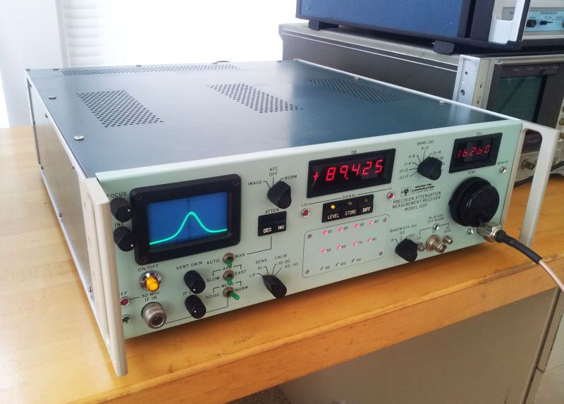
That’s the gem, receiving at about 16.260 GHz.