
With the recent repair of a Mettler AE analytical balance, I never thought that the schematics would be available and obtainable anywhere. Maybe even the Mettler corporation only has some dusty copies in their Swiss secret archive. But, as luck would have it, a very kind reader provided some of the schematics to facilitate repair and understanding of the working principle.
At the time of the balance, like, 40 years back, it was still a challenge (maybe it is still challenging today), to build a mechanical system and ADC converters that are stable in resolution and drift to 1:10E7 counts and similar.
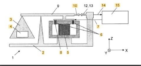
The basic working principle of force compensation and precision balances has long been known from the relevant patents, Sartorius, Mettler, Shimazu and similar. There is position sensor that can very precisely detect the position of the balance, to better than a micron. Then, there is a force coil, a magnetic system similar to a loudspeaker to compensate the force. Various levels and hinges may be involved. Then, there is a current regulation, a current reference, and a ADC to deal with the conversion to digital information. There are also normally temperature sensors to compensate temperature drift. Normally, the balance is continuously measuring the reference current and the coil current, and for best results, always leave it plugged in. Inside, there is some quite heavy aluminum case not only as an electrical shield but to avoid temperature imbalance. Accordingly, even when “switched off” by the front panel switch, these balances are actually internally on, doing their thing.
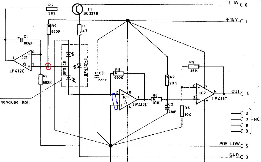
Key part is the position sensor. It works by a differential pair of photodiodes, and the total photocurrent is kept constant by active regulation (the left opamp), both diodes work vs. ground in essentially short-circuit current mode. Note that at the red point, the currents of both diodes add up (as total flux reaching the diodes) and need to cancel out the current from the 680 k resistor to 15 V rail. One diode, of course, has a resistor in the feedback loop of the right opamp (transimpedance amplifier) that will drive current through the 680 k resistor in its feedback loop to cancel out any differential current of the two diodes (to keep the negative terminal at virtual ground). More precisely, both diodes are keep at constant bias (short circuit) even if the photo current various or is unbalanced. Such setup has very linear response over several tens of micrometers. Rather than the BPX48 diode, you can use better Hamamatsu parts. Normally a small slit is used to illuminate the diodes, say, 30 um. You don’t want to make it too small, otherwise, there will a lot of light needed with associated heat and drift, and you don’t want to make the slit to wide otherwise sensitivity will be less. Certainly good to use a high efficiency light source like the SFH401-2 (15 degree emission angle, IR emitter).
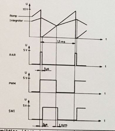
The ADC, it works by an integrator, a reference current source (based on a LM399 high precision reference in some balances!), and a few current switches.
The magnetic coil current is simply regulated by a control loop that has some lead-lag elements similar to a PID regulator (otherwise such loop won’t be stable because of the nature of the electromagnet and phase angle).
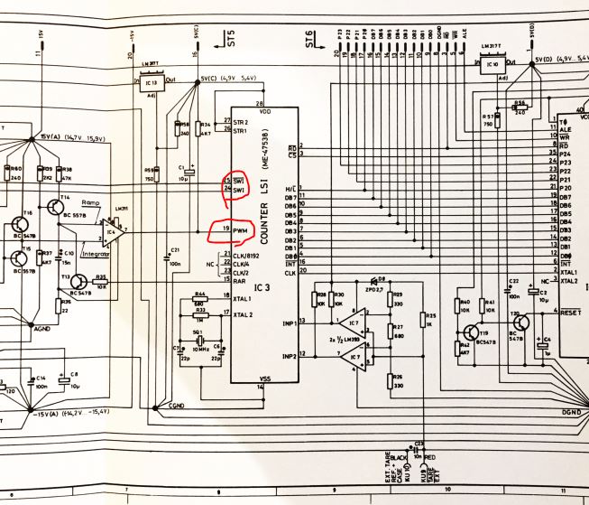
Such system is integrated in a custom ASIC. Probably the best solution at the time.
An interesting solution for sure! Given the custom LSI I cannot help but wonder how many of these balances were produced. Non recurring expense for designing such an LSI were quite high (“been there, done that”). My own Mettler is a far simpler and far less accurate affair, not for the highest accuracy laboratory use but more for general purpose lab use. But more that accurate enough for using it to produce my own photographic B/W developer.
It used to be the industry standard balance for many years in various models so probably there are many. Still popular today in some labs. There are some switches and pins on some of the mask programmed Cpus to reuse in various models. Even the serial interface has a mask programmed Cpu. Better not make mistakes during programming. Similarly, for the ADC, Prema company build precision voltmeters on the same principle at the time, all with their own Asics. Later, they became an Asic company rather than expanding the test equipment business.
The balances weren’t cheap at the time maybe something like USD 10k in current dollars. They were also adjusted at the factory for temperature compensation of zero and scale, so probably one or the other engineer hour went into it during assembly. So probably a 25 Dollar Asic came cheaper than a 100 Dollar 20 bit analog frontend from Burr Brown or similar enterprises at the time.