
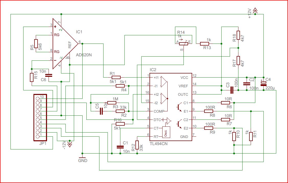
The current regulator – this module converts the current setpoint signal (from the position regulator) into a drive current for the magnet coil. This is achieved using a TL494 PWM modulator chip, and two BUZ11A (50 V – 0.045 Ohm – 26 A) MOSFETs, each operated at 50% duty.
Brief description:
The current setpoint signal is connected to JP1-9, connected to one of the comparators of IC2, the TL494. The other comparator is used as a current limiter: the sense wires of a 0.05 Ohm shunt in the coil supply line are connected to the input of IC1, and intrumentational amplifier, via JP1-7 and JP1-8. You might have to change the amplifier gain by modification of R5.
Current setpoint is adjusted by trimmer R14. JP1-3 and JP-4 provide the gate drive for the two BUZ11A MOSFETs. The drains are connected to the coil, the sources are joined at the current shunt.
Directly, at the MOSFETs, which are mounted on a heatshink (but don’t actually get hot), together with current shunt, there are several electrolytic capacitors (low ESR type), and a 1 µF PP cap (polypropylene dielectric, for pulse current service) in parallel with the (non-regulated) magnet supply. In combination with a strong and fast Schottky diode (anode at the MOSFETs, cathode a the positive supply), these caps are the best protection against any transient voltages when the coil is de-energized.