We are talking 2-18 GHz here, and getting signals clean and strong, at such frequencies, can be quite expensive.
I didn’t want to go for any harmonically multiplied generator, but something straightforward, reliable, and easy to fix. Looking around, I have a Systron Donner 26.5 GHz synthesizer, model 1026, which is great, but I don’t want to add it to a fixed purpose rig. And it is somewhat tricky to control.
Another choice, a Gigatronics 1720, great device, but I don’t know how to remotely control this instrument (it has IEEE-488 bus, but is somehow non-reactive to it, and I don’t have a full manual that shows all the codes – if you have a 1720 manual, please let me know). Also, I need this gem for various test tasks that require one or more stable microwave sources.
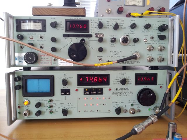
Finally, I scored a Micro-Tel SG-811 on xbay, not quite cheap, but still a steal. It has all-discrete type construction, several YIG oscillators, a tracking YIG filter, and (limited, see later) remote control functionality. I also has a high-precision output attenuator, so setting any level from +10 dBm down to -120 dBm will be no issue, and allow measurement of even high-gain amplifiers, at any frequency. The unit needed some repair (nothing dramatic, fuse holder, and some minor items) and alignment – one rainy afternoon. With some effort, I managed to locate a paper manual for the SG-811 (from commercial vendor, about 100 EUR!, but worth it), which made the latter task much easier. It may be noteworthy that the unit is ex-MOD, shipped from the UK.
So, the source question has been resolved.
For the receiver: there aren’t too many high precision microwave receivers around, the Scientific Atlanta 1711 (which is just the receiver, no digital amplitude measurement chain), and the Micro-Tel 1295 being the viable alternatives. Fortunately, I found a Micro-Tel 1295.
The Micro-Tel 1295. It covers the full 0.01 to 40 GHz span; 0.01-18 Ghz with the main unit, and 18-26.5, 26.5-40 GHz with two harmonic mixers, that – big luck – came with the unit, and are fully functional!
I acquired this unit already several months ago, and fixing it was no easy task. The -15 V rail was dead, due to some over-aged tantalum caps (interestingly, in the frequency display!).
The -15 V rail also controls the power supply circuitry itself, and any mistake could ruin the receiver altogether. But never mind, there are full schematics available. The power supply is of switching mode type, all discrete electronics with NE555 timer, transformer, and optocoupler feedback.
My only advice: don’t fix it in a rush, but take it step by step. Should any of you come across a 1295 with defective power supply – shoot me a line.
Here, a quick glance at the two gems: