
For the ultra-linear ADC endeavour: Generating low distortion sine waves is actually, down to about -80 dB, not really a challenge. Wien-bridge oscillators will to the job. There is a related, very popular scheme – the state variable oscillator, chiefly, SVO. It is more or less just a chain of 2 integrators, an adder, and some regulation circuitry, to keep the gain at exactly 1 and the amplitude stable. It will deliver 2 signals, at 90 degrees phase shift.
For general instruction, just have a look at the schematics of the Tektronix SG5010 Low Distortion Audio Oscillator, or the marvelous HPAKeysight 8903A Distortion Analyzer. There is also a very comprehensive article in one of the HP Journals, just have a look around the web, plenty of details out there.
For the design, I selected a UAF42AP for the integrator opamps, because this part is quite handy, and an MPY634KP analog multiplier to get the gain stable. The signal level is sensed with a simple opamp rectifier, and a damped low-pass is used for the gain stabilizer (leveler). The gain stabilizer by rectification, I just put it in as a temporary fix, lacking some analog switches (DG201) that will be used in a sample-and-hold circuit.
Also the UAF42 will be replaced later, most likely with some LME49710, which are currently resting back in Germany.
The integrator time constant of both integrator are controlled by 2 multiplying 12 bit DACs, AD7543JN. This will allow (1) tunable frequency, and (2) reduction of harmonic distortion by adjusting the tracking of the two integrators, with some inevitable differences of capacitor values, and so on. The frequency tracking will be step-wise, no change of any settings during the ADC sampling period.
A little draft (let me know if you need help reading – proper schematic to come, once design is more mature), just to help you understand:
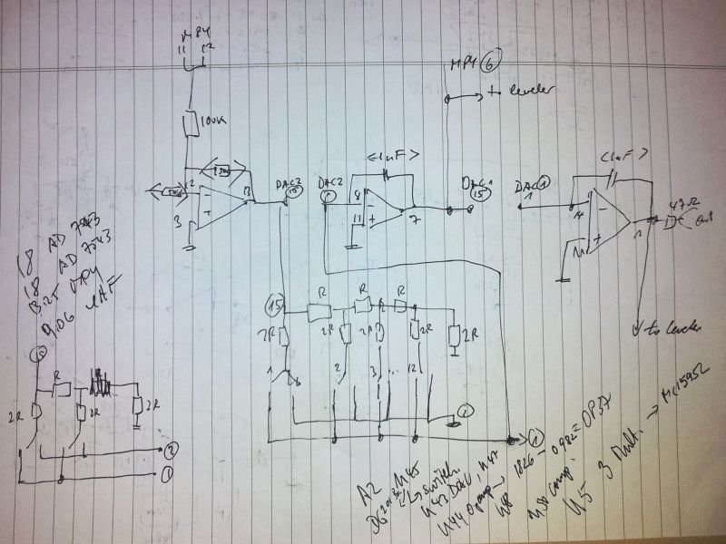
You can see the integrators, the resistive network of the multiplying DAC, and the output. Leveler and multiplier not shown. Both signals (0 and 90 degrees) are fed to the leveler circuit, to reduce ripple a bit. Very long time constants are needed, to avoid impact of ripple on distortion – will need to analyze, and replace with a better leveler circuit (digitally controlled sample and hold, on both the 0 and 90 degree signals). The leveler circuit will also generate useful SYNC signals for the ADCs – most likely, I will link the sampling to a multiple of the calibration signal or use the SYNC signals to discard measurements over certain portions of the sine waveform.
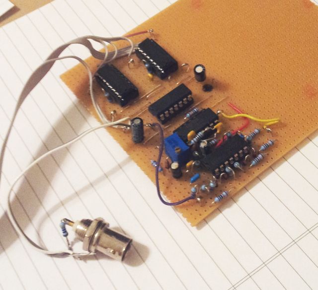
That’s how far things have advanced. It’s running with +-15 Volts, and 5 V digital supply, and controlled by an ATmega32L via USB. Later, I might keep the ATmega, and use this as a slave controller, via a serial bus.
Measurements to come. Stay tuned.