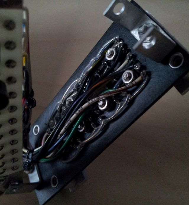
Finally, some time to deal with the MSR-902C repairs. After replacing the 7401 TTL, and a 7404 TTL, the band select logic seems to work well, except two bands. This could be traced to a dead transistor on the A3A5 band control board. Still a mystery, what caused all these defects? Tracing the line going to the dead transistor (which appears to be a simple +15 V on/off switch), it only goes to one place – a circuit far inside the receiver. As it turns out, this is a hand-wired circuit, not really a circuit board, but a piece of sheet metal with various solder posts. And, on the other side, two filter. One filter mounted properly, the other tied to it with some thread. As you can see, this holds the filter in place, but it can still move around the other filter – and cause a short on the 15 V rail, including the signal coming from the transistor switch.
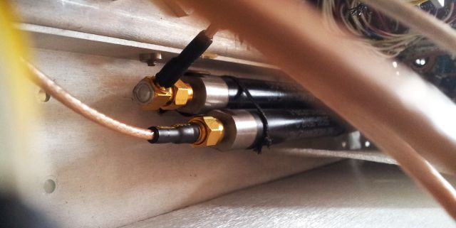

To avoid similar defects in the future, I put some plastic sheet around the filter, and fixed it in place with better ties.
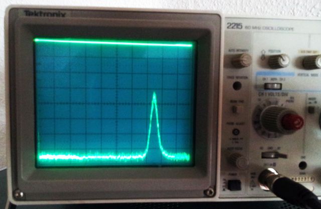
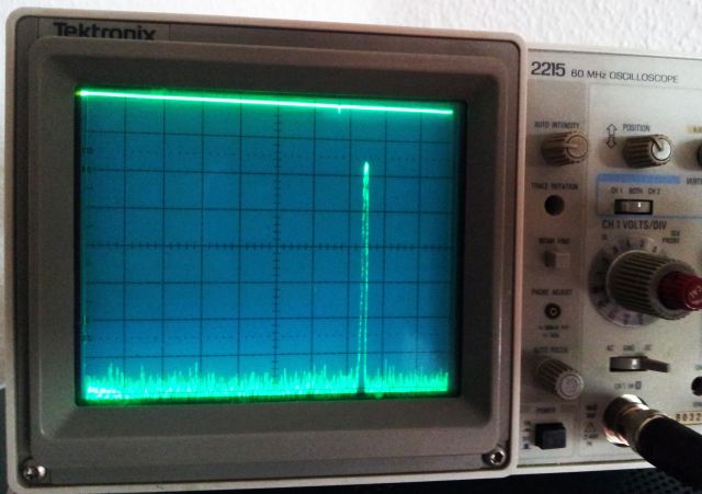
Finally, time for some alignment of the YIG filter, by using a fairly complex setup, a microwave signal generator, a scope to test the receiver output, etc. – see below picture.
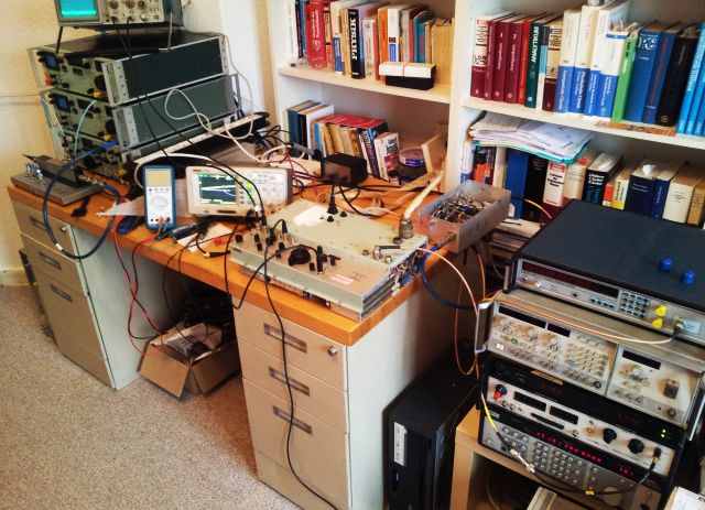
The YIG filter needs to be aligned for each band, same for the YTO band edge frequencies. This is all done on the A3B7 board. Not much adjustment needed, fortunately, only some fine tuning of the YIG preselectors.
Receiving… quite fun to operate the receiver, easy to tune over the full range of frequencies. Maybe this is what makes it so suitable for detecting microwave bugs.
Some last repair relates to the frequency display. It did work in some bands originally, not sure how the defect came about – maybe I slipped with a screwdriver, or some other mishap, or some already damaged part, I can’t tell. But now it only shows erratic values, and without a schematic, it is a tough task to fix it.
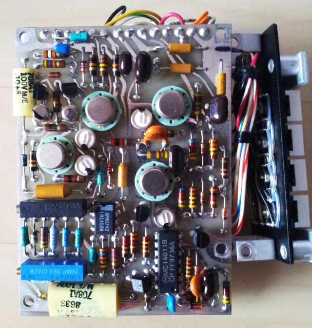
A fairly complex assembly, keep it mind, it is just a volt meter for the frequency display… so much easier nowadays…
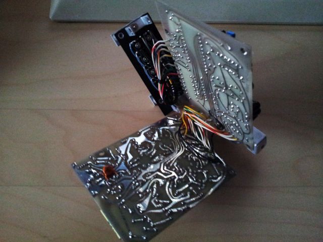
The LED display: hand-wired with Teflon coated wires. Sure, this receiver was never intended for the layman, but for some agencies that don’t care about cost and taxpayers’ money.
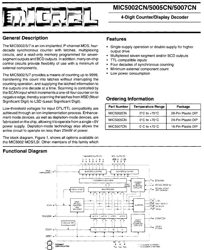
After some tests and checks – the voltmeter uses a voltage to frequency/time converter, and a MIC5005 integrated timer! Quite a nice and complex chip for its age!
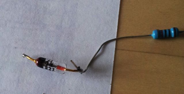
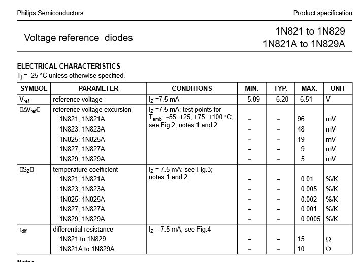
Two hours later – found the issue. A bad reference diode, 1n821. Unfortunately, no such diode in stock, but it is quite similar to the 1n827, only that the latter is more precise, and more expensive, and only a used part in my bin. But easy to check, just put a resistor in series, and run at about 1 mA, and check the voltage drop over the diode. All good.
Finally, reception is pretty good over all bands, no detail tests of noise levels done yet, but already now it is clear that this is pretty capable receiver, build with only the best components at a time – just the style is not quite service friendly.
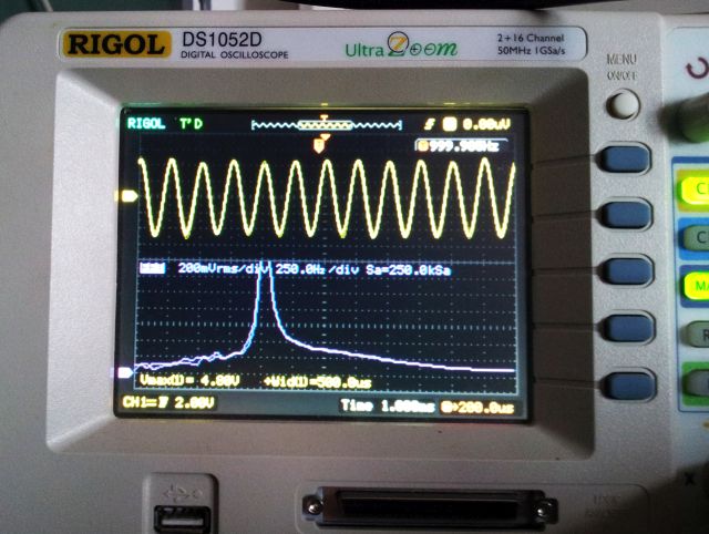
Demodulators work as well, receiving 1 kHz demodulated signal, all looking pretty good and clean.