The 3580A is a audio spectrum analyzer of the 1970s, and not only useful for audio, but anything that can be converted to audio frequencies (e.g., noise analysis of GHz sources, provided, you use the appropriate mixers). This marvel is not a FFT machine, but a discrete audio “received”, using a low-noise local oscillator, and covering a frequency range from 5 Hz to 50 kHz. The resolution filters are quarz filters, with bandwidth down to 1 Hz! Dynamic range is over 80 dB.
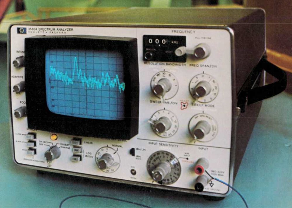
The device, it comes from my old university, and has been sitting there on the shelf for a while, not working. And in fact, it shows not many signs of life, it is not sweeping properly, and even in manual mode, it is not working reliably (not showing any reasonable signal, but there is some activity on the tracking output which suggests that the instrument is not all dead, also the “overrange” LED is working).
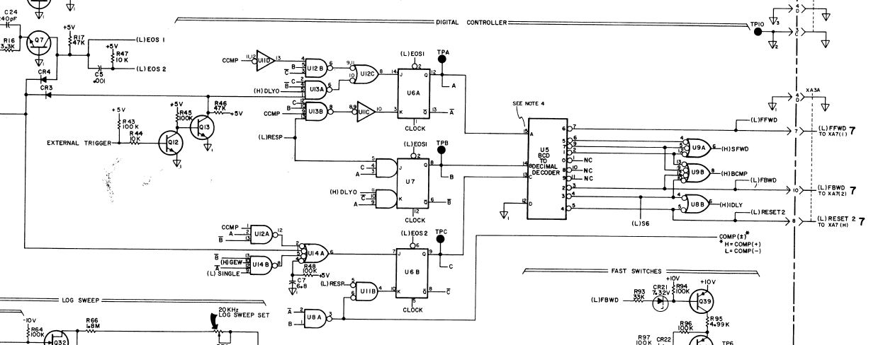
After some study and test it became clear the the issue is with the ramp generator. Unfortunately, it is not a simple ramp generator, as you can see below.
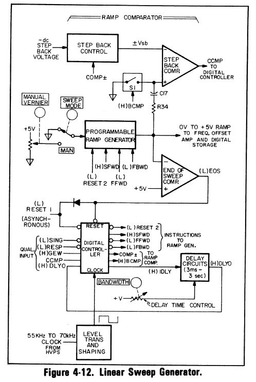
The main circuit is a capacitor being charged by a current source (mechanical switch with resistors).
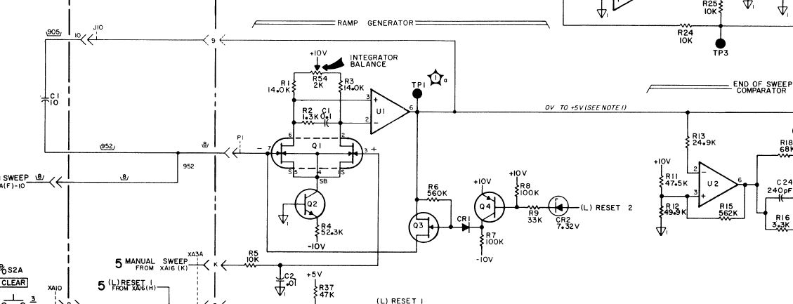
The voltage at the main capacitor, a 10 µF polyester hermetic cap (really high end with glass seal and metal case), is charged and its voltage amplified by a FET-opamp (the FET input constructed from a discrete FET pair, and a PTFE stand-off to keep this all really high impedance).
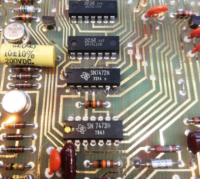
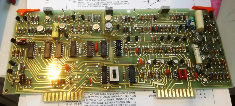
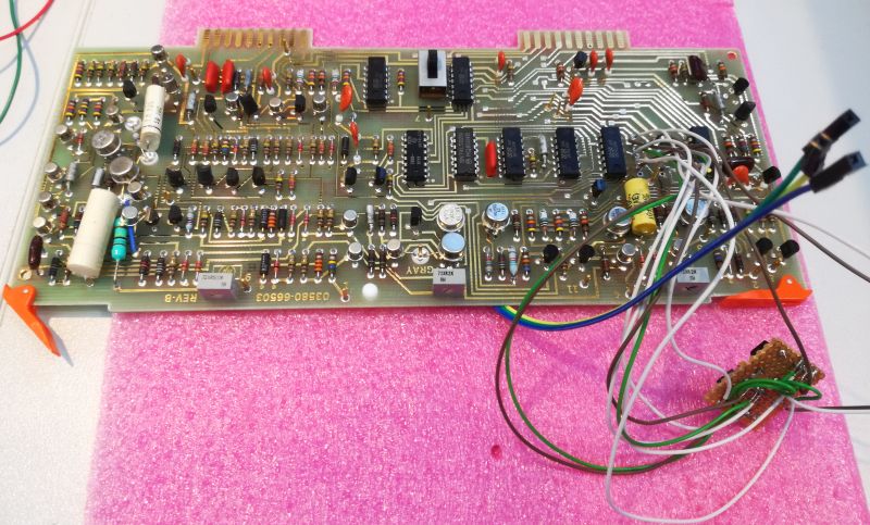
All the sweeting action is controlled by a state controller, more or less, a hardwired program with several TTL chips. It took me quite some study to understand how it is supposed to work. But fact is, it doesn’t. Clearly, the issue is with the A3 assembly. This must have been quit an expensive assembly at the time, with all the FET pairs and opamps. Still today, not an easy thing to fix.
At least, it is a beautifully arranged board, all gold plated and really smells like quality. So it is worth some time and effort to fix it.
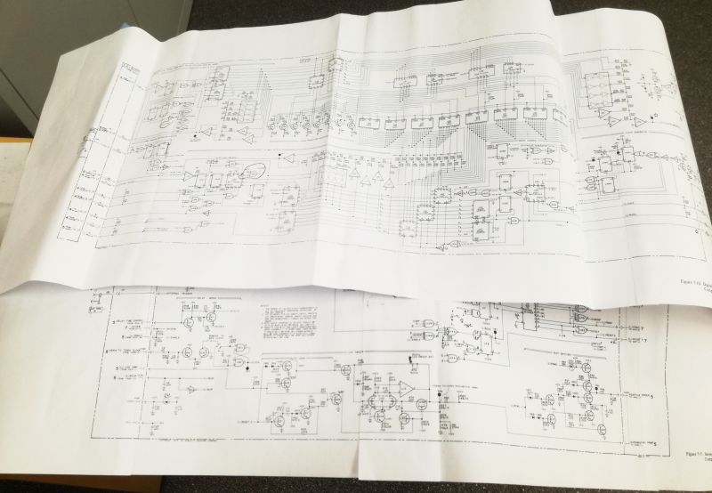
Key for such repair, at least in any reasonable time, are a set of good schematics. Fortunately, I have a set around and printed out really large copies – it is worth the effort, because without making some notes, you will struggle to keep all in your brain and still work on the circuit.
With no extender board available, just soldered some wires to the board to monitor the state of the main state counter, and some of its inputs.
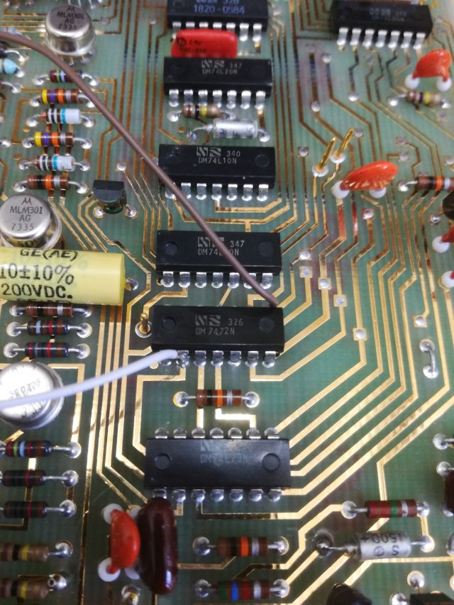
Hmmm, after a lot of probing, I was almost tempted to replace a good part of the TTL chips, because it is really hard to find the defect in such a complicated and loop-wired logic circuit, including its analog parts.
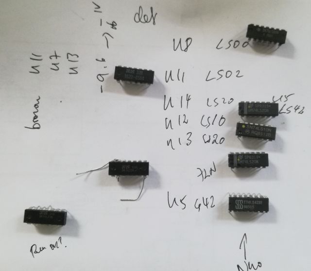
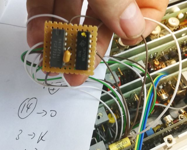
But after a bit more consideration and test, I decided to try a step-wise approach, starting from the most likely parts causing issues. One of the 7473 dead, no problem, there are spares around. But the next one – a 7472! This is an AND gated J-K flip flop, with three inputs to each AND gate… in simple words, something old, exotic, and rarely used. Went through all my piles of old boards and ICs, but no 7472 to be found! Quickly arranged a temporary 7472 – from a 7411 3-input AND gate and a 7473 flip-flop.
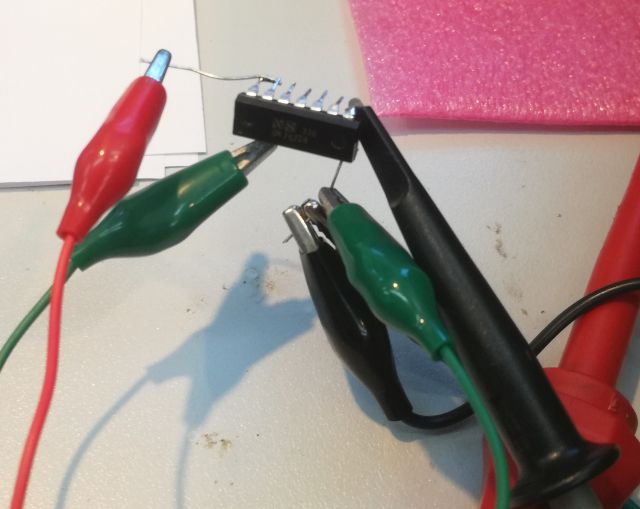
To be sure, I tested to old 7472 – indeed, it is not working.
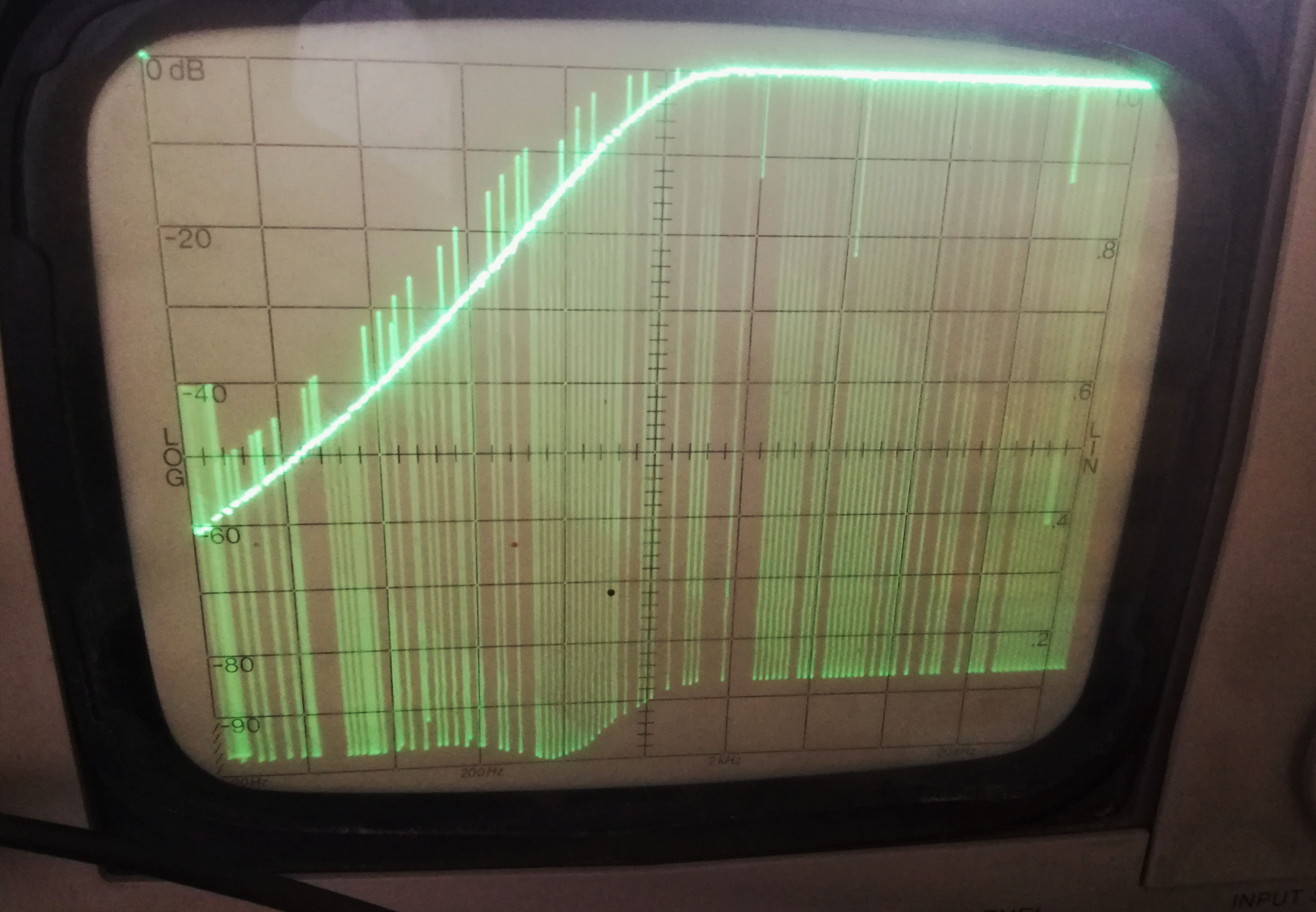
With the A3 board temporary fix, a quick test of the unit.
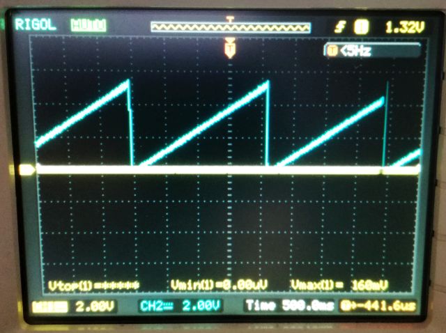
Unfortunately, still some issues, but is is sweeping:
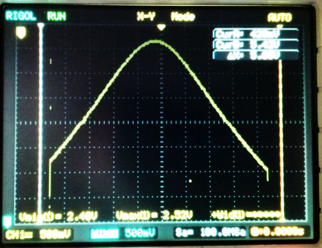
Display issue:
Check with a X-Y scope (on the rear outputs of the 3580A) – all seems good from the analyzer section, maybe some issue with the storage display?
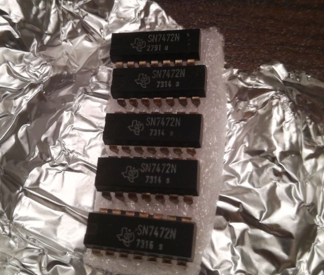
Finally, on xbay, found a set of 5 pcs 7472 at a reasonable price, from Spain! NOS (=new old stock), about the same age as the 3580a!
Some fluxing issue with the soldering of the old ICs (clearly seen at the 7473), beware! Use some good flux, or solder from both sides.