
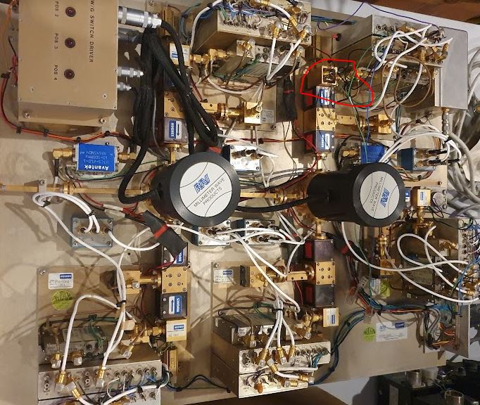
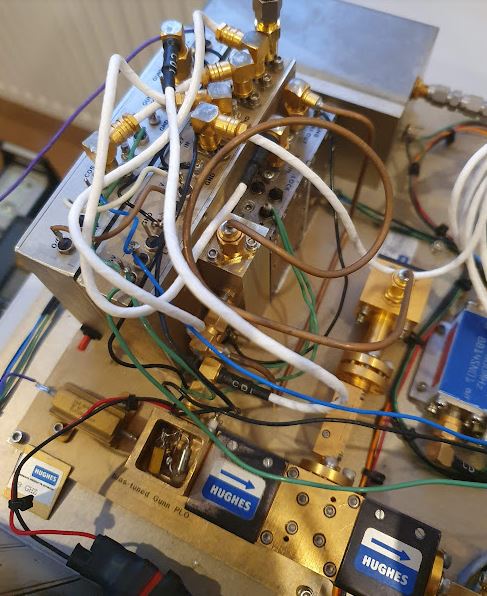
Recently I got hold of a really marvelous bit of kit, an assembly of millimeter wave phase locked oscillator, all the way from 60 to 89 GHz. It is already 35 years old, but all based on solid state Gunn/Impatt oscillators, so there is little aging. For each frequency (there are 5 discrete frequencies), there is a full assembly of reference upconverter (100 MHz reference to some intermediate frequency in the 6-12 GHz range), a voltage controlled fundamental oscillator (e.g., bias-tuned Gunn diode), the necessary isolators and splitters and occasional attenuator, along with a harmonic mixer. The IF is 100 MHz or 200 MHz, depending on the unit.
Only one of the oscillators has been more than 20 kEUR in 1988 currency, and there are five such assemblies on this plate, along with control equipment and power supply…
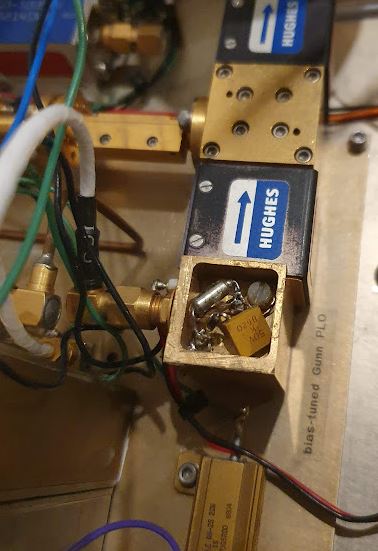
Only one of the sources is playing up, not achieving phase lock, it is the 79 GHz oscillator. Notably, some of the small screws are missing and the lid of the oscillator cavity has been removed, which points to prior repair attempts. The Gunn has a protection network, a 2.2 µF capacitor in parallel with a ~10 Ohms, ~470n series network — this is to protect the Gunn diode from the inductance of the bias current supply (when the diode snaps-off according to its characteristics, it will induce a very fast current spike that could increase the voltage at the diode above its damage threshold).
Upon close inspection, the 2.2 µF capacitor had been tampered with, bad soldering, only one end connected, and in reverse polarity (it is a high-reliability tantalum cap).
When checking the down-coverted output, there is no stability at all, it has a very strange FM modulation. What could be the root cause?
Checked a few items:
(1) Upconverted reference, 11.3 GHz (7th harmonic will be 79.1 GHz): it is a very clean and stable signal, well locked without any visible noise.
(2) Checked all the cables and connectors by pushing gently, no sign of any trouble, all unchanged.
(3) The supply voltages are all practically noise free.
(4) Also fixed the 2.2 µF capacitor at the gunn diode cavity. No particular effect.
(5) Disconnected all the phase lock, bias driver, and driving the oscillator from an external supply.

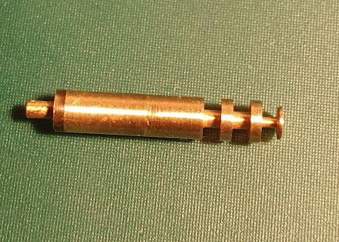
Finally, with just an ordinary power supply connected and the voltage ramping up (don’t ramp it up too slowly or let the oscillator sit in an unstable region or at the Gunn peak current for any length of time!), there is a stable (surely, non phase-locked) output, but none of the strange modulation. So it seems, the oscillator is good. But wait, with some wobbling and touching on the part, it is shorting out the supply. Hmm. Time to go a little deeper, and I decided to remove the biasing rod.
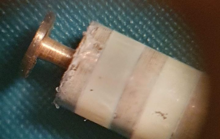
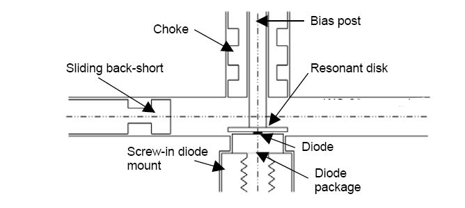
Just for explanation, the biasing rod is isolated from the cavity (the metal block holding the diode, with the waveguide cavity in the middle), and conducts the current to the diode, which is at the tip of a metal screw holder.
Under the microscope, the very thin isolating tape (looks like some PET/Mylar transformer tape) is quite damaged and some metal of the bias rod exposed. Also the spring holding down the rod on the diode (which is fixed by a nylon screw) can contact the case easily. So all was newly isolated, and the screw and spring positioned carefully. Surely with all the soldering at the capacitor, things may have shifted a little. At least now no isolation problems any more. Sometimes when switching the oscillators on the assembly, the 79 GHz signal is not coming up, the Gunn drawing much less current. But it can be fixed by just power cycling the assembly, so it seems to be some rise time issue of the power supply.
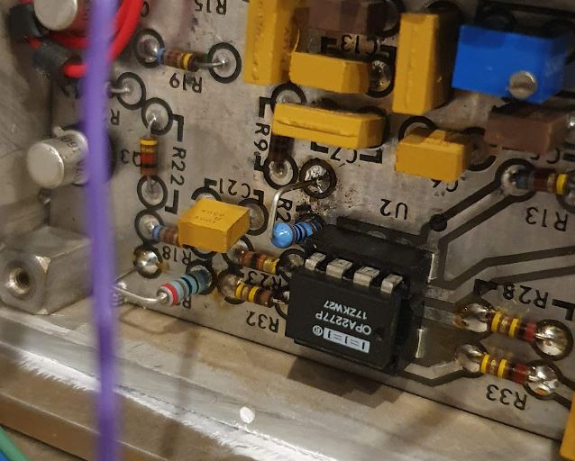
This is the driver circuit, it has a hybrid high-speed Kennedy electronics 722 amplifier, but the low frequency path is a common NE5532 low noise opamp.

After checking around the low frequency path, the opamp seems to introduce some noise, note that for this level of noise at GHz levels, a few millivolts are more than enough to cause a lot of disturbance.
Fortunately, the opamp was socketed, so I replaced it with a OPA2277, which has about the same noise compared to the (low-noise) NE5532, and much lower offset voltage drift, and 40 dB better CMRR, excellent low frequency characteristics, and lower gain at >1 MHz.
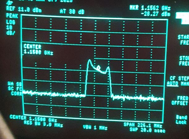
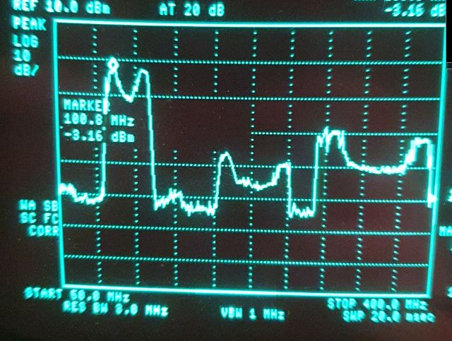
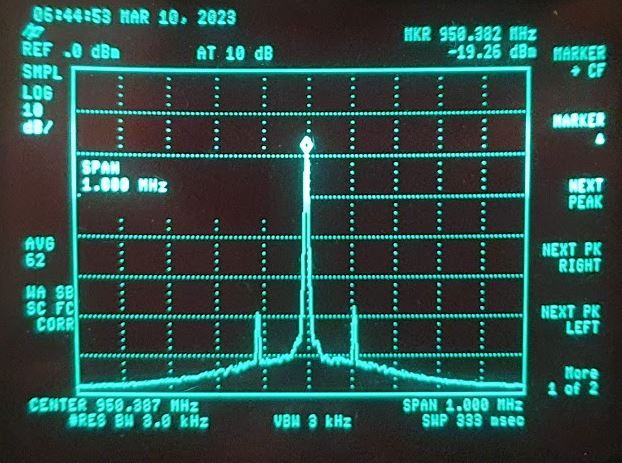
Now, with stable current drive, we can measure the output power (downconverted by an harmonic mixer driven by a 11.45 GHz source, 7th harmonic: 80.15 GHz — shown is the minus mixing product, i.e., 79.0 GHz correspond to 80.15-79=1.15 GHz).
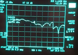
You can see clearly, the oscillator has good power from 79.1~79.25 GHz, but falling down just around 79.0 GHz. Note that at such high frequency, every mW counts…
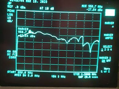
After some thinking, I decided to try to lock at 79.2 GHz, and as it turns out, it is working fine at that frequency. With the 11.3×6=79.1 GHz, and 100 MHz IF, it works out, and the PLL doesn’t seem to be affected, regardless if you use the minus or plus side IF.
The IF signal can be probed conveniently at a test port, it is pretty clean.

Also the down-converted signals look good (this is 10 MHz span at 79.2 GHz center, corresponding to 80.15-79.2=0.95 GHz downconverted).
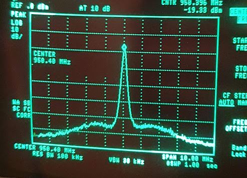
Also the close-in side bands are good and a very clean signal.
Wow! That is an interesting bit of SHF kit! Even just counting the waveguide parts it is still worth €€ for the avid (e.g. ham radio) tinkerer.
Any idea what it originally was used for? I am also curious where you found id, assuming that can be revealed of course.
MfG,
Wilko
Spectroscopy!
Hello Simon, again a nice work on a historic piece of equipment. BTW in case of E-band, the progress due to P2P link band 71-76/81-86 GHz and radar band in the middle 76-81GHz leads to introducing very sophisticated integrated commercial parts from cheap SiGe integrated RX /TX for TDD links up to similar parts from Hittite/AD. It was a nice time and the 1Gb link developed in our company with about 20dBm power is still in production… We use multiplication of LO by 8 from 9 or 12GHz depending on used subband.
I would love to do more experimentation in the E band with some recent devices, at least I now have various test gear to detect such signals and measure attenuation and phase shift.
Also it seems a nice connection of precision machining and electronics.