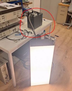
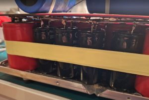
A very unusual and dangerous repair, a defective photo flash. This is a professional unit, for use in photo studios. Generally, these units work by charging a big capacitor bank to 300-400 VDC, and then discharging this energy in an instant through flash bulbs. This unit has 10 pcs. of 2450 µF capacitors, charged to 360 VDC. About 1600 Joule, which makes this unit very dangerous, I would strongly discourage anyone not familiar with power electronics to even open the case.
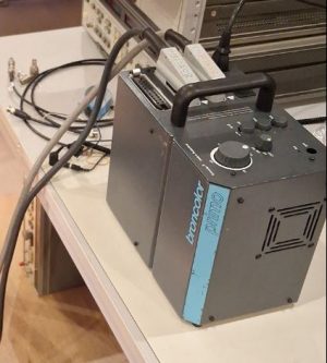
For its size, it is quite heavy unit, and has a 16 Amp fuse, it will recharge quickly, drawing substantial power for a short time.
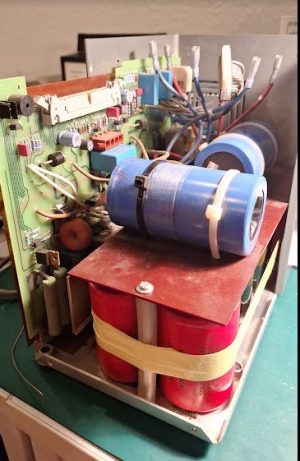
Inside are 12 large capacitors, 2 for the charging voltage stabilization, 10 for the capacitor bank. After duly checking the caps and their safe discharge state, I tested them all, each individually. 3 were bad: 1 completely disconnected at the terminals, 2 with no capacity, worn out.
Flash capacitor need to withstand high discharge current, so we cannot just use any ordinary cap but need to source “flash capacitor” – found reasonably priced one from China, because there were other faults with this unit besides the capacitors, there was no reason to by expensive caps first, without knowing if this unit can be fixed at all. Unfortunately, there are no schematics available.
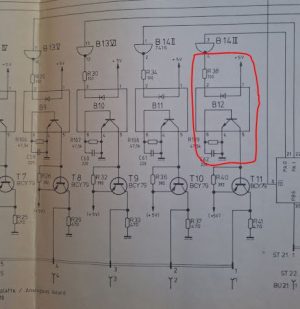
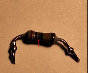
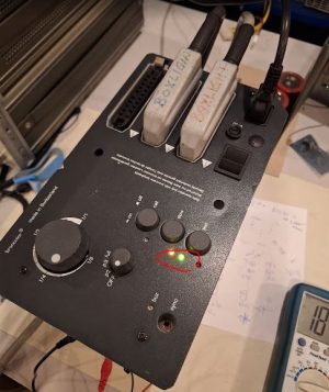
Studying the electronics, there is a primary thyristor (TXN1012) switch DC stage, a type of coarsely regulated power supply. This had a blown transistor in its control circuit. Failed by arcing. Fortunately, I was able to still read the color rings under a microscope, and replaced the part and an associated Zener diode. Also the thyristor and a MOSFET in the thyristor were replaced (the MOSFET tested good, but I didn’t want to take a risk).
The replacement caps have 2000 µF. 3x 2450=7350, 4x 2000=8000, so I decided to install 4 of the 2000 µF capacitors (2450 µF were not available easily). It results in about 5% higher energy in one bank, good enough.
After some hours of complicated failure search and repair, some very careful tests (checking if the caps load symmetrically, which they did), finally the green light of the “flash read” LED was lighting up.
The flash worked – but only for a short time, then: SMOKE from the flash box. Expecting the worst, opened it up right away. Surely, first removing the cables from the capacitor bank.
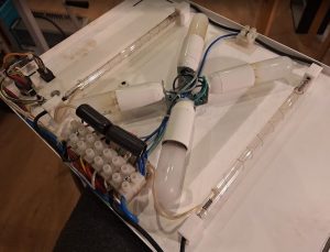
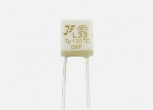
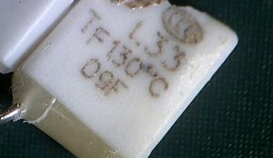
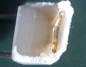
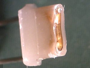
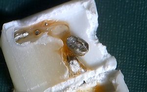
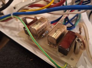
Inside of the flash box, 4 Xenon? flash bulbs, with spiral trigger electrodes. The high voltage trigger transformers are right inside the flash box. The smell is awkwardly familiar: an exploded Rifa safety capacitor. 0.1 µF, 1000 VDC.
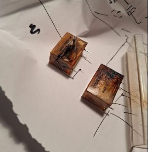
Fortunately, it failed open, as it is supposed to, lots of bad smell but no damage or fire. There is one capacitor for each bulb, a total of 4 (2 sets).
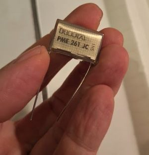
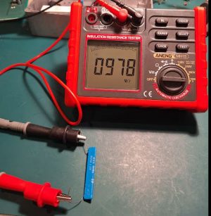
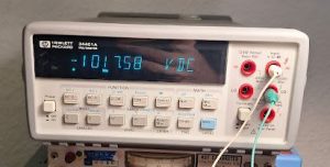
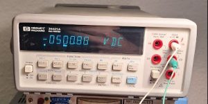
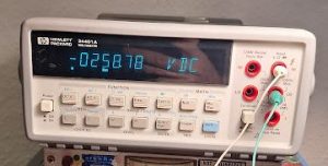
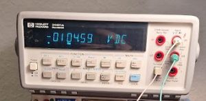
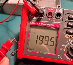
I cleaned up the mess, ordered 4 original Rifa (now KEMET, but they still print “Rifa” on these), and soldered it all back together. The other 3 were electrically still good (tested for leak resistance several MOhm, and isolation test passed at 1000 VDC), but had many cracks so I replaced all capacitors.
Eventually, all is working again. There is a built-in studio light, quite fancy unit. Hope the repair will last for a while!