All posts by Simon

NOAA basics – tracking satellites

Before we start, satellites are little devices that move through space attracted by gravity, in our case, gravity of planet earth. Some are stationary – they rotate along with the planet’s rotation. Others move in different ways. The NOAA satellites, are of the latter kind.

Therefore, first step, is to figure out where the NOAA satellites are, and when they are in sight – only then, we can expect a signal. Easy enough. Downloaded “Orbitron” software, which is really great, and updated the “TLE”s – the so-called two line elements that describe the movements of a satellite.
Make sure to set your location (and time) right. And get familiar with UTC time scale.

APT – this is just the codeword for the downlink protocol. It has been around for a long time, and its days are counted – new satellites use more powerful protocols, more bandwidth, to get high resolution picutures down. But I’m glad there are still a few up that transmit pretty nice pictures, in a not too complicated format.

Using SDRSharp and the little Chinese magic “DVB-T” stick, a piece of wire was all that was needed to get some first signal received. So, in fact, there are satellites above. Let’s get a bit closer!

Modern times: ADS-B via SDR R820T, RTL2832U

To cut a long story short – the SAT tuner receiver is working great, but here, close to EWR, JFK and LGA airports, there is just too much going on in the air for the ATMega8 to handle, via the serial link – quite a few frames are dopped during transmission. So, I could go into developing a decoder using a more capable processor, which should also improve frame integrity by faster sampling, and so on. I figured, this may take several months to get it started, and in the end, not much learning – others have done this before, and it really only about faster processing, than anything else, and buying a designated ADS-B receiver, well, that’s not much fun.

Well – why buy a designated receiver? Good friends told me, I should look into some Chinese magic gadgets, called DVB-T/DAB/FM USB on xbay, for about USD 10 delivered. These little devices really are nothing short of a miracle, containing a silicon tuner, in this case, a R820T (which is arguably the best type of SDR USB stick you can get for anything related to ADS-B), and a RTL2832 chip. The RTL2832 is more or less just a reasonably fast 8-bit ADC that can -as some really clever people have figured out before-feed the data streem directly to USB, and into a computer. The rest is history, em, software, therefore, the thing is called software defined radio, aka, SDR.

20140825_130821

Tutorial (you will find many more comprehensive around):

Step (1) – install the generic WinUSB driver (Zadig installer), don’t bother installing any of the software supplied by your prefered Chinese source of little gadgets.

Step (2) – install SDRSharp, this comes with ADSBSharp. ADSBSharp will feed all received frames to a designated network port

Step (3) – install ADSBScope, or any other ADS-B plotter you like that can serve as a client and listen to a given (local) network port

The old-fashioned approach: modified SAT tuner for ADS-B

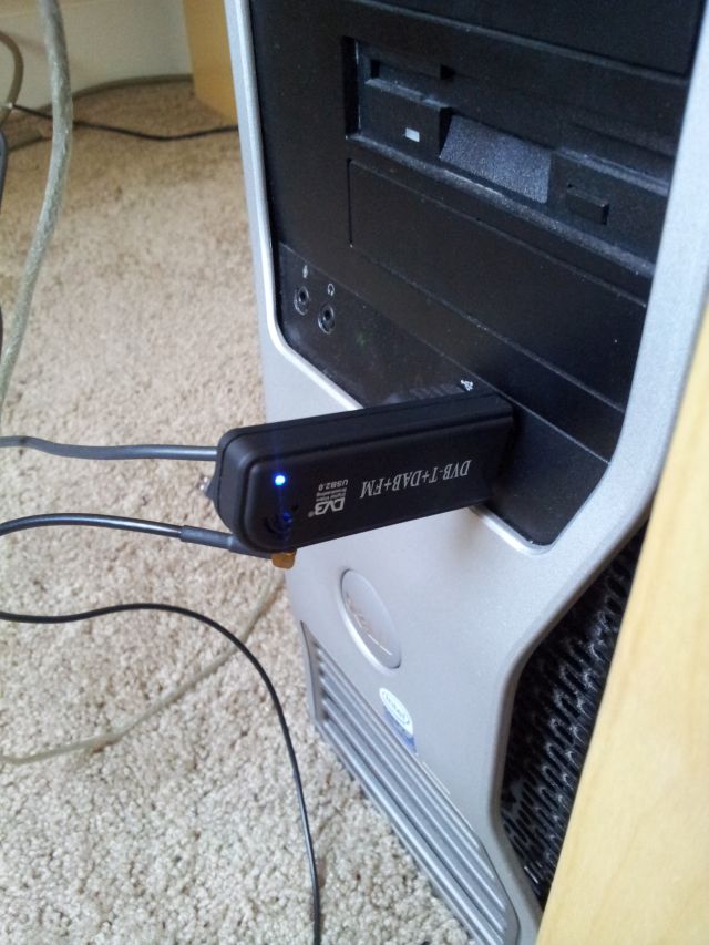
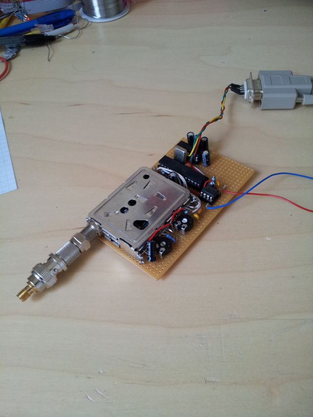
Please check out the web, you will find numerous sites that will tell you how to turn a surplus SAT tuner into an ADS-B received. Don’t fiddle around with old analog stuff, get one that has a proper demodulator (preferably, TDA8012), and a build-in PLL. The PLL – it’s easy enough to find out the pins going to the SCK, Data In, Data Out lines – it should be a TSA5055 running off a 4 MHz Xtal reference.

Step (1) – get the PLL to work. Just have a look at the TSA5055 datasheet, and clock in some divider data that make sense, and check with a receiver, or spectrum analyzer, if the LO is giving some useful output. The TSA5055 has a fixed:512 reference divider, therefore, with a 4 MHz reference clock, the phase comparator is working at 7.8125 kHz. For ADS-B reception, the main divider is set at around 12666 divisions, plus the :16 build-in prescaler, equals 1583.25 MHz LO frequency. Keep in mind, the SAT Tuner IF chain has a 480 MHz SAW filter, with about 27 Mhz bandwidth – therefore, I suggest to tune the receiver a bit to the edge (like 1103.25 MHz in my case, for 1090 MHz reception) – this will improve the shape of the output signal.

Step (2) – disable the AGC circuit of the TDA8012 by lifting Pin 9 of this circuit off the board (use a SMD soldering iron, and good lighting!). I connected Pin 9 through (unused) Pin 2 of the tuner to the outside world (33 k to VCC).

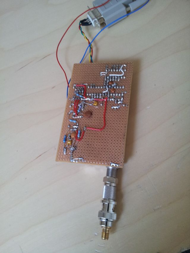
Step (3) – Now, some soldering – you will need a low pass and comparator circuit to convert the video, Pin 6 of the TDA8012 to digital output. The low pass is a simple 1 k/82 p RC network, the comparator a MAX903 (which is fairly high speed can can handle the 1 µs pulses, with fast risetimes at the output). Note that the MAX903 is open-collector, so you will need a 10 k pull-up resistor at the output.
20140825_130754

20140825_130804

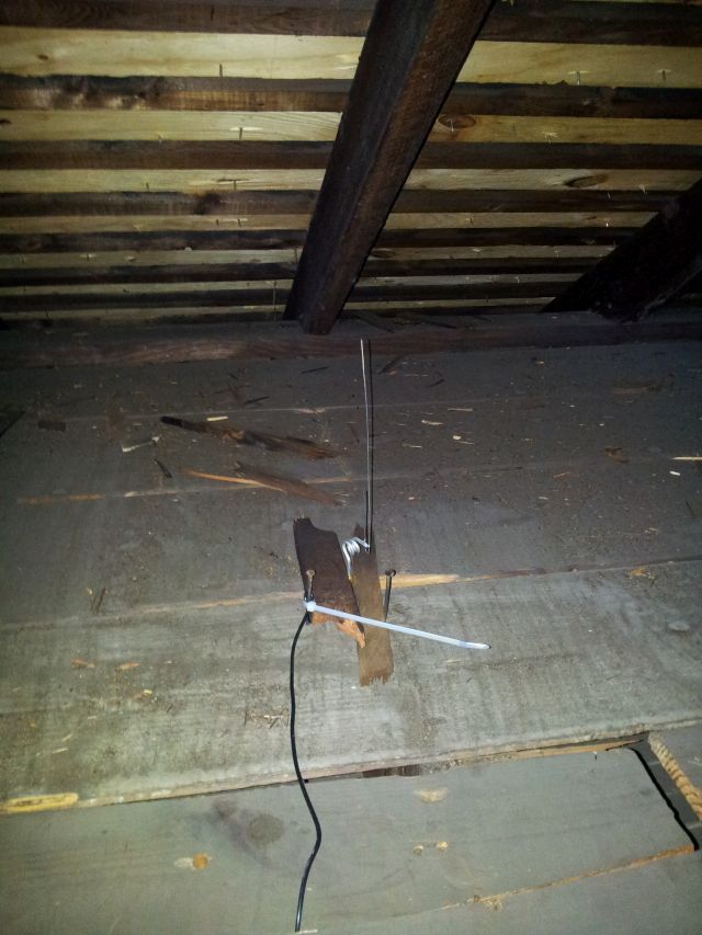
Step (4) – connect to antenna, check with a scope (best a digital storage scope, triggered by an ADS-B “frame start” pattern) for signal at pin 6, and tune the LC tank circuit of the TDA8012 a bit, until the signal is clear. Just a bit of bending of the coil with a non-metallic tool is all that is required, if any.
Reception quality can be optimized quite a bit by adjusting both the LO frequency (around 1580 MHz), and the TDA8012 LC tank oscillator.

Step (5) – add a bit of peripheral circuitry – a MAX232 for the serial interface.

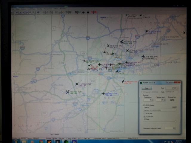
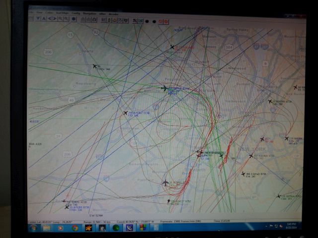
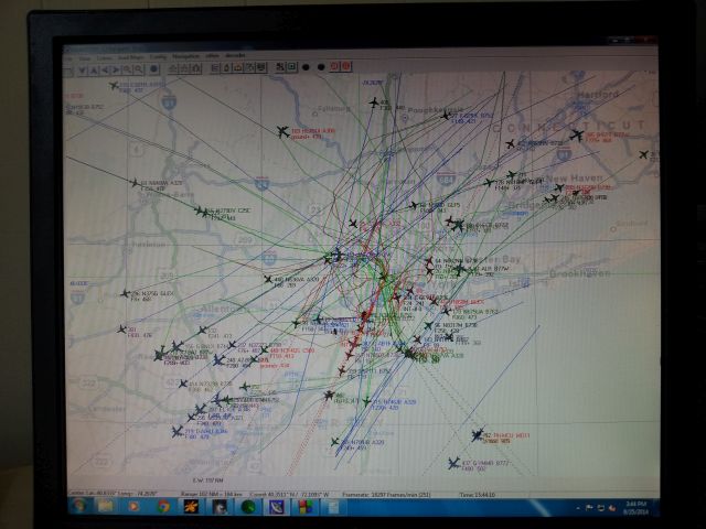
Decoding is done with a bit of assembler and C code, using a ATMega8-16, run at 16 MHz. Frames are being checked real-time, and only the “good” ones forwarded the PC software, via a 19200bps (slow!) serial link.

Antenna!

You might ask, how to receive 1090 MHz? – fortunately, enough, not all that difficult. It’s old news: the best receiver is a good antenna. No need for anything fancy here, a bit of copper wire (silver plated, but any wire will do), and a piece of coax will do.
If you want to fabricate one for yourself – the coax needs to be connected about 10-12 mm, from the lower end of the loop. Short pole is 55 mm, long pole 205 mm, in my case – with the shield soldered to the short end (doesn’t really matter too much). The coax has a few turns, acting as a simple balun (you might want to put some heat shrink tubing over the semi-rigid coax, to prevent shorting of the loops).
20140825_130602

FYI, I found that it works well in the attic. So there is no need of weatherproofing, and the neighbors aren’t getting too curious because of numerous antennas sticking out of your home….. The roof isn’t all that strong, plywood and tar paper; both keep out the rain, but not the RF waves, fortunately enough…