HP 8569A Spectrum Analyzer: A shaky fix

Coming back to an earlier post, 8569A CRT DONOR NEEDED, I was desperately looking for a new CRT for an old 8569A.

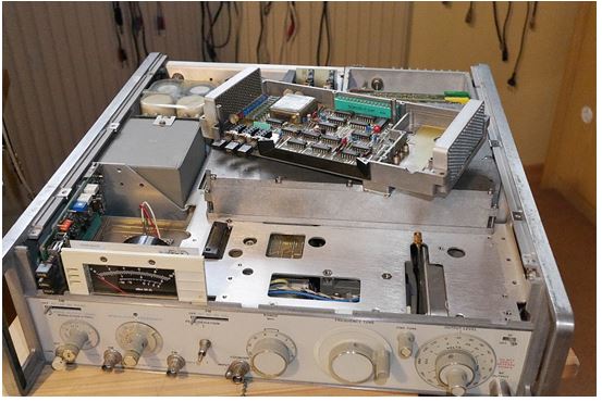
After some hints of a kind reader of this blog, I decided to give the box another try, and removed the CRT. There was nothing wrong with the grounding, or the Aquadaq coverage, but at least, there was a sign of defect – a glass chip rattling loose inside the CRT. Turned the CRT with the face to the ground and gave it a few good hits. Reconnected everything (with carefully inserting the CRT back in the box). There result – all working great again. Seems that a piece of glass got stuck in CRT deflection unit, and caused the distortion of the screen. Appears to be a pretty rare defect, but at least, the CRT should be good for now (unless you sit the 8569A on the back feet so that the glas piece can get stuck again in the deflection unit).

Still, some more trouble with this unit:

(1) Rebuild the switch assembly and reference level encoders, about 3 hours of work, and a lot of tiny M1.2 screws, etc.

(2) Some start-up issues: the 8569A would sometimes only start when the “reset” button is pushed. Checked the EPROMs – and, one of them corrupted. Replaced the whole set, just to be sure. These are all TMS2516 EPROMs (let me know if you need the good binary images).

8569a differences

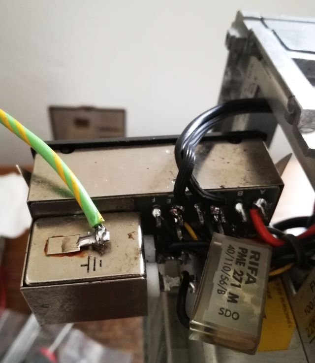
(3) Still more tedious work, replacing the mains filter… many wires… and the mains filter X2 cap.

dav

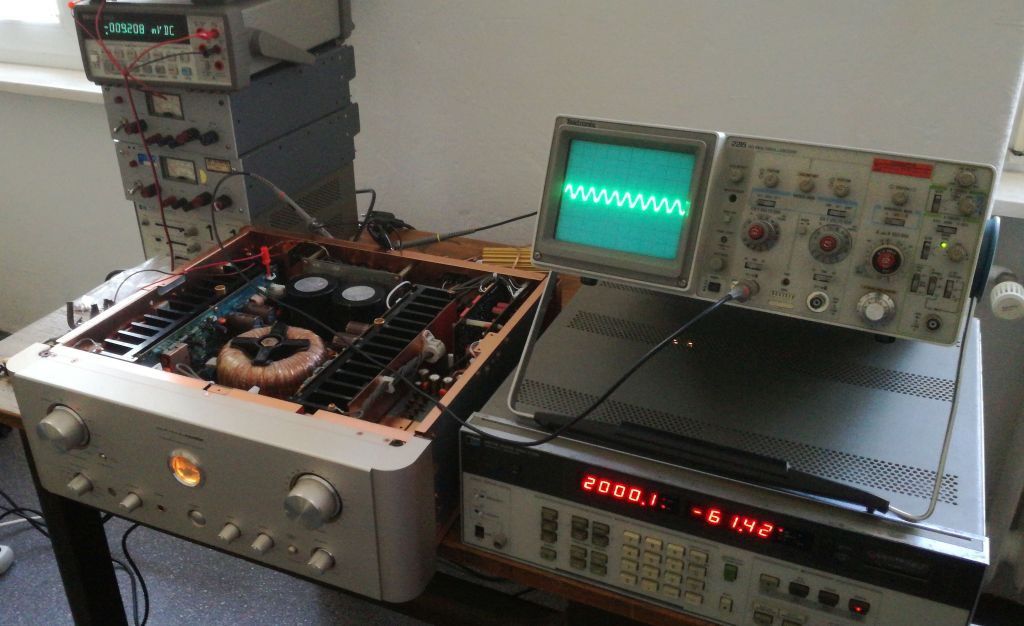
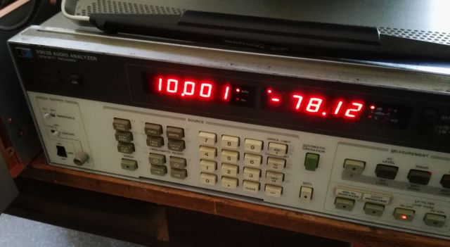
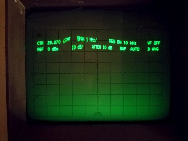
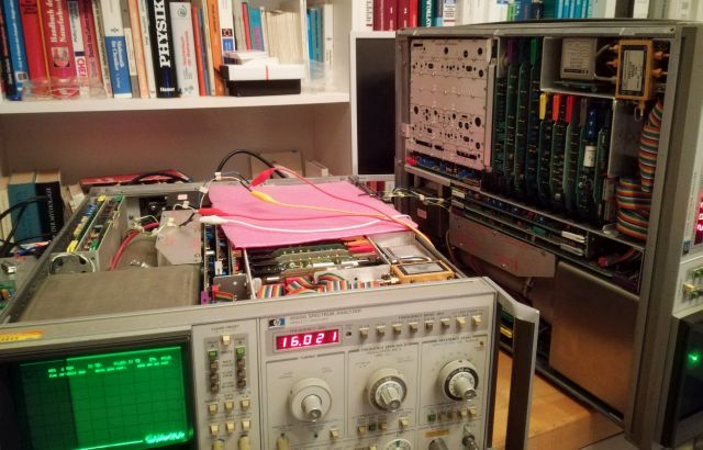
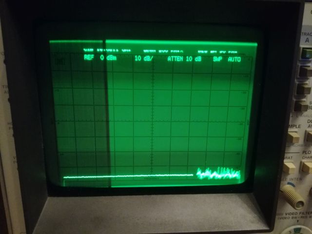
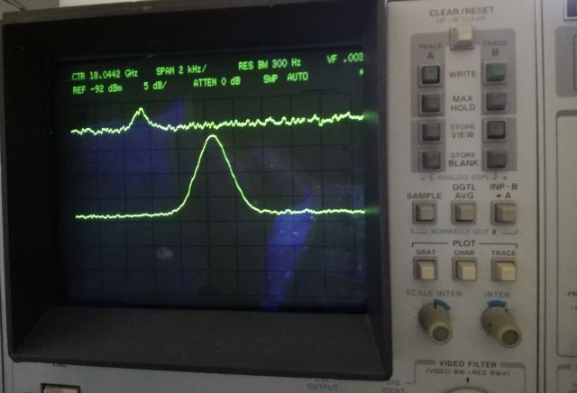
Now, some quick tests: sensitivity test of all bands, and at 18 GHz, all to specification!

dav

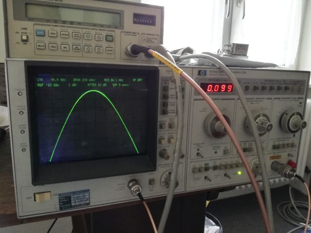
Also checked the power reference, with the best two powder meters at hand, all reading to at least 0.1 dB with no adjustments.

sdr

This repair is done, but please, don’t put this 8569A on its rear feet!

Marantz Stereo Amplifier PM-14 MkII: explosive silicon

A heavy beauty, a Marantz Amplifier, PM-14. Certainly worth a detail look – according to the owner, the left channel is not working, and some smoke escaped along with burned smell.

No wonder – the two main transistors of the left channel are blown, say, exploded. And, upon further inspection, also the traces leading to the transistors, at least some of the traces – evaporated.

bty

This is the full view of the left channel amp (right channel is quite similar, but mirror image – some components placed at slightly different positions.

bty

bty

Some burnt resistors replaced…

bdr

The board is double sided, but not through-plated, and the quality, well, is not all that good – needs to be soldered with care, otherwise the traces will lift.

After some further checks, fitted a new set of transistors (ISC brand, China – still better than some fake “Sanken” transistors), but to the biggest disappointment, when switching on, these exploded in a loud BANG when adjusting the idle current. Well, turns out that also one of the earlier stages had a short transistor 2SA1145. More testing revealed another defect, a dead Zener (exchanged both Zener, to make sure that there are no issues with temperature drifts etc.).

With all these things fixed, time for a test, using a HP 8903A, and a scope. The HP 8903A is really handy, if your are into any quality audio repairs.

The test setup –

nor

Distortion measured at several frequencies, and several volts RMS at the output (using a 5.6 Ohm dummy load – just because I didn’t want to take out the 4 Ohm precision load for these power levels). -80 dB total harmonic distortion+noise, not bad.

bty

bty

bty

The front view – it has the classic Marantz indicator, for best sound, wait until it has warmed up.

bty

nor

As a reference, just in case you need it, the service manual Marantz PM-14 Service Manual. Or, just send me a message, or the come along with your dead amplifier.

HP 8640B Signal Generator: A new divider

The veritable 8640B generator, a marvel of engineering and still remarkable design today, it has reached an age where repair is often hampered by obsolete parts – sure, you can search for a donor unit or some NOS parts in some far away places, but in other cases, it is more practical to replace the circuitry with some new parts, especially, if the circuit is easily tested and verified.

This applies to the pre-scaler/frequency counter, which is an essential part of the 8640B, at least, if you want to use its internal counter (the 8640B is not PLL controlled).

Thanks to a kind contributor, Bodo, here a brief story of the repair:

(1) Symptom: the 8640B showed irregular frequency counts, completely unrelated to the expected output frequency. First consideration was a defective band switch (which has a cracked Delrin gear), but test with a spectrum analyzer revealed a perfectly good signal. Connecting a 0-10 MHz signal to the external counter input also gave perfectly good counting.

(2) After study of the schematic, the issue could be traced to the RF scaler, which is located in a die-cast cavity. Note that there are various versions of this board, but all feature some ECL logic ICs, with high power consumption.

prescaler 8640b assemblly

(3) Further tests showed that the first divider, :2 was defective.

(4) There are several ways to fix this. Here, the complete divider chain was replaced by a U644BS, available in DIP8. This IC is quite common in old TV tuners. There were also several projects in popular electronics magazines of the 90s to use the U664 as a pre-scaler up to 1.3 GHz.

Datasheet U664B U664BS

Picture of a random tuner from the web, using a U664B:
prescaler tuner

With the external input, the 8640B is counting up to 900MHz, sensitivity is better than -25dBm.

Note that the U866BS is self-oscillating (not a problem, because the 8640B oscillator is permanently attached for internal counting).

The modified prescaler board under test:

prescaler 8640b u664bs under test

One side effect is the much lower temperature of the RF scaler (much lower power consumption of the U664BS vs. the old ECL logic).

Finally, this is the schematic, the signal is connected from a-INPUT to b-OUTPUT.

prescaler 8640b schematic

HP 8569A Spectrum Analyzer: Any organ (ehh, CRT) donors out there

This 8569A came from the US, purchased by a local HAM operator, and in need of repair. Some switches don’t move nicely, so it seems liked a regular repair job of a 8569A.

First issue, 5 minutes after turn-on, where not the switches, but a blown mains capacitor (aging X2 grade capacitor). Well, this is easy to fix.

With the instrument powered on, it quickly became evident that the there is some distortion of the display, in particular, in the upper section of the CRT. This is not a common fault, and hard to explain other than by a broken deflection system of the CRT.

To be absolutely sure that no other assemblies are causing this defect, the X-Y deflection signals were coupled to a working 8569A, and indeed, no distortion visible.

The CRT display of a working 8569A – with the X-Y signals of routed from the unit that shows the distortions:

Sure, the display is not quite synced (also because of the extension leads with alligator clips). How to proceed? Well, this will need a 8569A CRT for repair, from a donor unit. Let’s hope, at least for the HAM friend that one will come around soon.

Workshop upgrade: Light fittings, and luminous efficacies

With the workshop basic repairs complete, how to set up a cost-effective lighting system?

Some items to consider
-I will be working there mostly after work, late in the evening, and mostly in the dark winter months. So I need daylight and bright light to keep focus.
-Diffuse light along will not be enough. I like the feeling of incandescent lights, so there need to be some work and bright direct lights.
-Some areas, like the stair, will need a separate light, which needs to be “ON” immediately after the switch is pushed. Same applies to the other lights – there should be no dimm start-up, flicker, or start-up delay.
-Light level needs to be high, because the main purpose of this room is the assemble, fix, and test high frequency/microwave assemblies, and fine-mechanical devices.
-Because this is a hobby, we need to keep expenses down, both for the initial cost (light fitting and lamps), and the running cost – electric power cost.

This is a plan of the room layout, rectangles mark the position of tables.

Essentially, two kinds of light sources have been considered – T8 fluorescent, for the background illumination, 8 pcs. 25200 lm total (EUR 5 per piece, including lamp and electronic started – a bargain). And 4 PAR38 30° LED down-spots (these replace the 108 W halogen lights, and have still have a nice glass body).

licht parathom

These are about EUR 13 per piece, and the light fittings are simple screw sockets E27 size, EUR 1.50 per piece.

licht raumplan

Some calculations done – total of 31 kilo-lm, 363 Watts (which is quite precisely found when checking the total current to the workshop with a wattmeter). ~85 Lumen per Watt, which is a very good value.

We will need to check the actual luminous intensity at the work surfaces later, because the lumens of the fluorescent tubes is not all going downwards (some reflected from the white ceiling and walls, some lost in the light fitting).

licht efficiacy

Life time these lights are rated for 25000 hours (LED), or 12000 hours (T8 tubes). This means, 3000~6000 hobby days (counted at 4 hours), so there should be no need to change these light bulbs and tubes any time soon.

New test lab and workshop: Renovation update

It has been a bit quiet here recently, not because of lack of activity, but more to the opposite. Currently, my workshop and test labs occupy on room in an appartment, 3rd floor (2. OG in German counting), and 3 basement rooms (mostly for soldering, assembly, and mechanical fabrication; plus 2 basement rooms in a house 2 hours drive from here… with some of the not-so-often-used heavy metal working machinery).

After some negotiation, I was able to get another room, which is on ground floor, well heated and rather constant temperature all over the year, and is has daylight – this all in a beautiful building that is even listed in the historic monument directory of the state. It has about 28 m2 floor space, and quite ideal for my needs to have a clean working area, for assembly of equipment, and detail testing. It is also much closer to the soldering workshop and parts storage in the basement, and will safe me from walking up and down 3 floor several times a day, during the final assembly phase or during repair works, which often require a combination of soldering, and difficult testing that could only be done so far on the 3rd floor. The basement is great, but it is too humid for operating vector network analyzer, and the like.

Now to the laborious part, the renovation. The had been used in the past as a meeting room for a motorcycle club (probably, in the 80s), and later as a workshop for remote-controlled model aircraft. During the last 3 years, it had been mainly used for storage, with the floor cover, walls etc, all aging away. Also, no internet connection of safe electric outlet available in the room. It took about 7 full days of hard work to get it up to requirement, including, removing all the junk, cleaning and fixing the walls, door, and wooden panels, removing several layers of old floor covers, and putting it all back together again. Another 3 days for all the cables, in particular, the network cables (all done using CAT7 LSZH 4x2xAWG23 S-FTP; one short section is CAT6 CCA PVC shield) and ethernet (CAT6) wall outlets.

Here a network map, mostly for my own reference, with the two servers (HTTP, SAMBA), running at 192.168.130 (this is the active server, a Dell Optiplex FX160 – it uses an ATOM processor, running Ubuntu, and is a really power efficient way to run such a system, 2 TB RAID0), and 192.168.77.140 (arctur, a Dell Poweredge server, 2×3 TB RAID1, used for backup of the active server, and also as a backup webserver in case of hardware failure or the FX160). All the switches were selected for low power consumption, to keep this green and low running cost. There are two WLAN transmitters, so now there is good bandwidth all around the (large) house and even in the basement and garage.

The WAN connection is via a cable modem, which is located in the 3rd floor apartment (2. OG), and works at 100 Mbps down, 6 Mbps up (this is good for now, usually getting abot 80~90 Mbps down, and the full 6 Mbps up, probably upgrading to a 100/100 Mbps connection next year).

A quick test of the network speed – by measuring the transfer speed from and to a ramdisk on the acrux server. Getting 50~70 Mbytes per second, from all locations of the network. That’s certainly fast enough.

werkstatt network map

This is a view for the power distribution, and network distribution box.

Weber Q100: BBQ repair and Q-burner

These days, fully occupied with workshop renovation and extension, and with spring gardening activity. One item that can’t be missed in an allotment garden definitely is a BBQ. Well, there are 2 coal-fired BBQs already, why not add a (gas powered) Weber? Only downside, these come at a quite significant price tag, and most times we will be using the charcoal grills anyway. But recently, opportunity came along, by the kind offer of a friend who upgrades his Weber, and was looking for a new home for his Weber Q100, albeit, in non-working condition (“it doesn’t heat up properly”).

This is the full view, including the stand, and a standard propane bottle already connected.

Based on the data of the Q100, no need to run on special Weber gas, or Weber gas cans.

sdr

This is the gas regulator I am using, just ensure it is 50 mbar, and has about 1 kg/h max flow. That’s plenty for the Q100.

dav

After 1st inspection, it is clear that the burner (stainless steel pipe in Q shape with many holes) is not in good condition. Several outlets blocked up. Usually, first recommendation is to scrub with a good stainless steel brush, WHILE the burner is in operation. This will burn away all grease and particles. Tried, but a bit too much residue to make this work.

Replacing the burner – certainly, an option, but costly, and these Q burners appear to be in short supply as spares.

q100 brenner

For cleaning of the Q-burner, following recommendation:

(1) Remove Q burner from BBQ
(2) Clean thoroughly with a wire brush especially at the side that has the holes
(3) Clean inside, by knocking on it with a piece of wood (brown dust will fall out), and with any kind of small brush or wire you might have at hand.
(4) Put in dishwasher to remove as much grease as possible, clean with some methylated spirits and/or acetone. If not properly de-greased, you will have trouble with the next step.
(5) Check all the holes by using a 1 mm twist drill. Make sure not to enlargen the holes but just to remove and solid residue.
(6) Clean with pressurized air or similar.
(7) Mount again.

dav dav

Also make sure to clean out the “venturi” section and wire mesh at the inlet.

dav

Mhh, still no good flame. Seems the Q100 is not getting enough gas. You need to check the orifice.

(1) Remove the gas inlet unit (the assembly with the knob to regulate the gas flow, two screws).
(2) Remove the orifice (which has a hex outside, usually, glued in with some Locktite). Don’t break any of the plastic parts.
(3) Clean out the orifice with air. No wire! Check visually.

To avoid blockage of the orifice, it is advisable to never connect a dirty gas pipe to the Q100 (some spiders might have crawled inside), and to cover the gas inlet of the Q100, if you need to remove the gas pipe for some reason. Best method is to leave the gas regulator and pipe/gas tube permanently connected.

q100 orifice

Now, after all this work, the Q100 is on flame again. All burning nice and blue.

sdr

Just after a minute, already heating up quite a bit. Now we have to put it to a real test next weekend.

dav

Solar Power to Electricity: Around-the-year analysis

Undoubtedly, a garden house will need most electric power in summer, because this is the time where you have long, worm evening. In winter, if you really want to stay in the garden house, better to switch the lights of and hibernate anyway.

So, how much yield (kWh) do you get from a photovoltaic system, located in Ludwigshafen, Germany? Well, there are very precise calculation models around, based on actual data. You only need to know the location, inclination and direction of the solar panel (and hope there is no shade!). For my location, about 8.4080 East, 49.4897 North, Orientation 192 degrees (SSW).

Then you go to Photovoltaic Estimation, and type in these numbers (select “stand-alone PV”).

Also, you need to know the Wp rating of the the photovoltaic cells. In the given case, we have 1 module “Siemens M55” (this has been around for a long time, datasheet of a current equivalent Siemens SM55 Datasheet), and a second one, quite similar, but slightly larger (need to find out the model number), all in all, 120 Wp estimated. The system also has lead acid batteries with total of 190 Ah capacity (C/100 discharge rate), but I just assume 170 Ah.

solar siemens m55 data

Feeding the various data into the calculator, it’s a really great tool!

garten solar calc tool

Total energy that can be harvested, per day:

garten total pv energy

Now, lets be wasteful and consume an average of 400 Wh per day. That’s enough to run some lights, and a sizeable fridge all day.

garten 400 wh

garten 400 wh graph

A bit more conservative scenario, running an energy-efficient small fridge, and some lights (sure, you can also charge some cellphones or run a laptop computer).

garten 200 wh calc

garten 200 wh graph

Now, lets check if the battery will running low – just changed the discharge limit threshold to 20%.

garten 200 wh 20pct cutoff

Still good, seems like we will have plenty of electricity during summer the summer months – in winter, we will just switch off the fridge, anyway, it is the best time for hot rather than cold drinks.

Standalone Photovoltaic System: lead acid energy storage cost

For any standalone photovoltaic system, a battery is essential, because electricity is most needed when the sun is not shining. With all the many battery types around, lead acid type batteries still appear to be the best choice for a low-tech system in a harsh environment like a garden house.

First, we need to understand that the cycle life of lead acid batteries strongly depends on the degree of discharge (DOD) per cycle. I.e., a battery rated as “120 Ah” would be only discharged by x% of its total capacity, and last much longer than with a full discharge every cycle.

This is the battery we are talking about – quite impressive packaging, no wonder, because there is liquid sulfuric acid inside!

mde

It is a N120S NRG Solar 12 V, 120 Ah, “Deep Cycle” battery. About EUR 75 if you buy it a the right spot.

mde

Some average life cycle data vs. DOD% for lead acid batteries.

solar cycle life2

With cost, DOD%, etc, you can easily calculate the total energy stored over the cycle life of the battery. Time-wise, the battery can last about 8 years, at least according to the manufacturer’s data. So, with about 100 cycles maximum per year, one cycle per day (unless earth rotation will pick up dramatically…), no particular useful life beyond 800 cycles.

solar cost

With these data, it is quite clear that for the type of battery brand I am using (which is not the best most expensive super grade solar battery), running at 20~40% DOD will give quite OK life time expectancy, and cost even lower than domestic/grid power here in Germany, at least with the paid-off solar cells and charger.

solar cost per kWh vs DOD

Sure, measures will need to be taken to avoid full discharge of the battery in winter, e.g., by disconnecting all major consumers, and just allow for some LED or fluorescent lights, and maybe, a few cellphone chargers.

Allotment 44 (Parzelle 44): Gardening, rather than soldering!

In these days of global trade, endless supply, and magnificent business opportunities, why not take a step back, and spend some time preparing the ground, in the the literal sense. This time of the year is great for such activities, and after several months of winter, working outside in the fresh air is certainly a recipe to keep good health and to enjoy life with family and friends.

Long story short, after passing the formal application procedure and test, we are now the proud owners of a garden allotment, number 44. In German, Parzelle 44 (Kleingartenanlage am Riedsaumpark, Ludwigshafen am Rhein, Germany).

solar orientation plan

The last owner could not maintain it for the last 2 years, so, it is in a bit desolate state, but nothing that can’t be fixed, and with these pictures being a few days old, it is now looking already much better.

This a general view of the allotment, 300 square meters total, a bit over 3200 square feet.

dav
dav

It also features several buildings: a garden house (stone-built, dry, and in good shape, just needs a bit of paint), a summer kitchen and workshop (wood frame construction, behind the house), and a tool shed (other side of the house), as well as a rather spacious patio. Enough space to stay there over the weekend, or to have extensive BBQ with a whole soccer team.

sdr
sdr

Needless to say, it is a garden house, there is no connection to the power grid, or to a gas pipeline – at least, we have tap water! All else will need to be served by propane bottles, and by a photovoltaic system. Sure enough, no need to upgrade this to a too high level, with the main residence just a 10 minutes walk away, and we don’t want to defeat the purpose of it, to be a bit close to nature!

Stay posted!

SimonsDialogs – A wild collection of random thoughts, observations and learnings. Presented by Simon.