Historic view of the workshop – Joh. Eisele Porzellan Grosshandel, Ludwigshafen

Found this great view of the current workshop (ground floor, left windows), dating back to before 1918! The building itself dates back to 1910, established by Joh. Eisele, who used to operate a major trading house for porcelain, glass, and stone ware, including a decoration workshop for such items.

While the back factory (with the railway tracks) is missing today (maybe bombed out it WW II?), the main building still exists today, in quite recognizable shape and form, even still with the name of Joh. Eisele in golden letters!

Micrometer and Force: a time-stamped interface

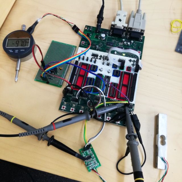
For a special application that I can’t name here, we need to measure both deflection (length) with about 0.01 mm resolution, and force in the range of 200 N (=20 kg). The force measurement is needed with a few 10s of Hz of temporal resolution, for deflection ~10 Hz will be sufficient.

All this needs to be accomplished at a budget, so I decided to use a China load cell (20 kg range), with an HX711 converter board, and a digital micrometer dial (13 mm range, 0.01 mm resolution).

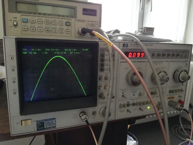
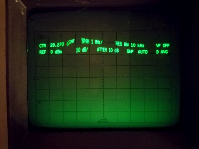
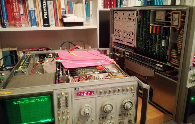
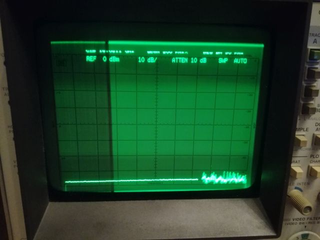
First, to the HX711. As per the datasheet, it can be run from an external clock source, not sure if this is necessary, but thought I give it a try. Spec range for the clock is up to 20 MHz (normally running at about 11 MHz), but the HX711 works well to 70 MHz and above. You don’t need to couple a lot of power, even at -10 dBm, it is still working. Anyway, by setting the clock control pin to HI, the HX711 will provide a data rate of 80 Hz. As with all analog-digital converters, there will be a trade-off for frequency vs. noise-free resolution, but for the application discussed here, even 10 bit would be enough, to serve the purpose.

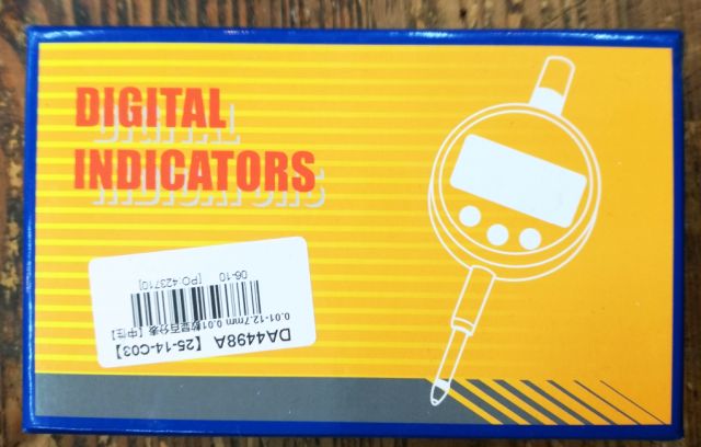
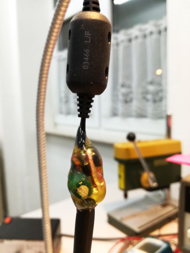
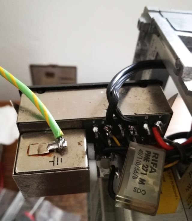
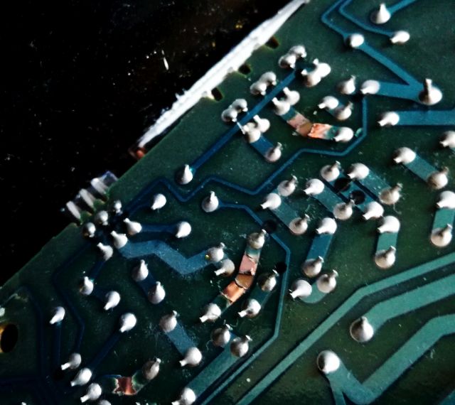
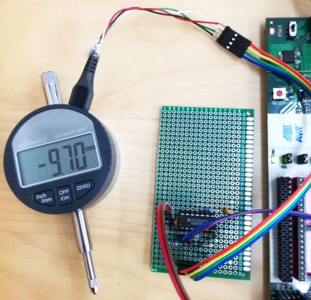
For the digital dial – unfortunately, the industry (the Chinese digital caliper and dial industry) has not yet come to a decision to use a commonly available connector to get the signal for a digital caliper or dial into a cable. At least, they offer various types of data protocols, and with not too much sense detective work, you can figure out how to interpret the data. I user a Micro-USB connector, carefully soldered to the data output pads of the micrometer dial.

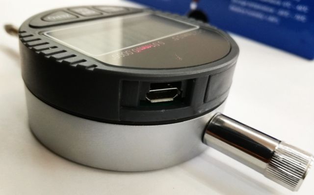
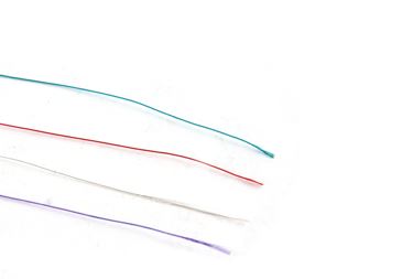
Some small wires were used to connect the USB connector to the board, to allow for some movement, and to ensure longevity even in an environment that has vibration, and people connecting the USB cable with not much care.
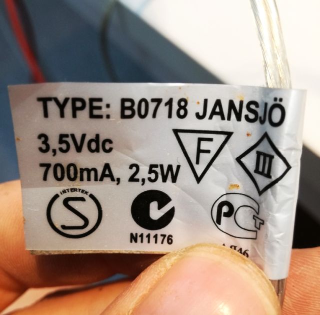
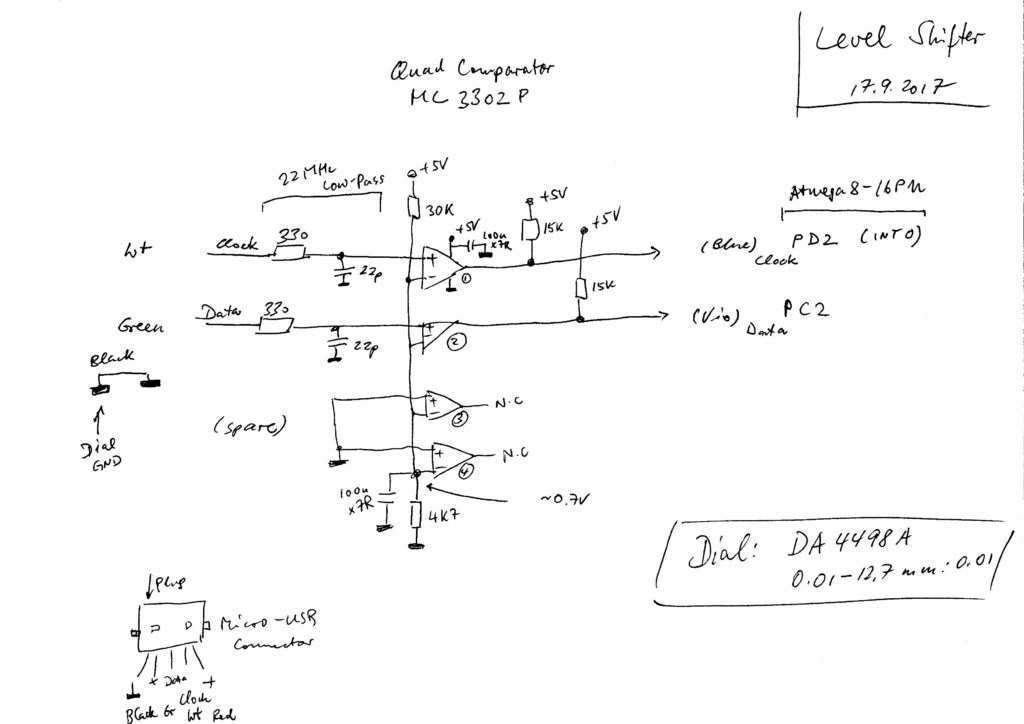
The dial is running on 1.5 V (a single button cell), so we need a small converter board, using half of a MC3302P quad comparator, to convert the 1.5 V logic to good old 5 V TTL logic. You can use any type of comparator of logic conversion circuit, even a single transistor may work. Anyway, I didn’t want to load the dial any more than necessary, and to improve noise immunity, added a 20 MHz low-pass (330 Ohm with 22 pF) to the input.

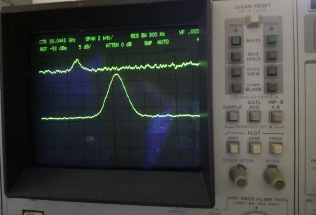
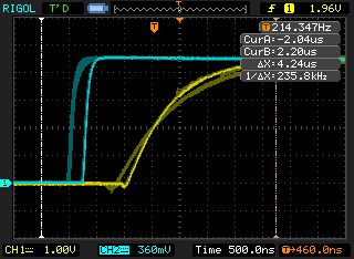
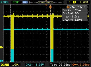
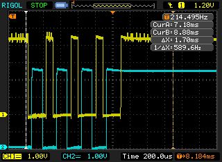
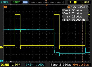
Here the rising edges, logic conversion board input (blue), vs. output (yellow). For the faster traces, the internal pull-up resistors of the ATMega8 were enabled. Not much effect anyway.

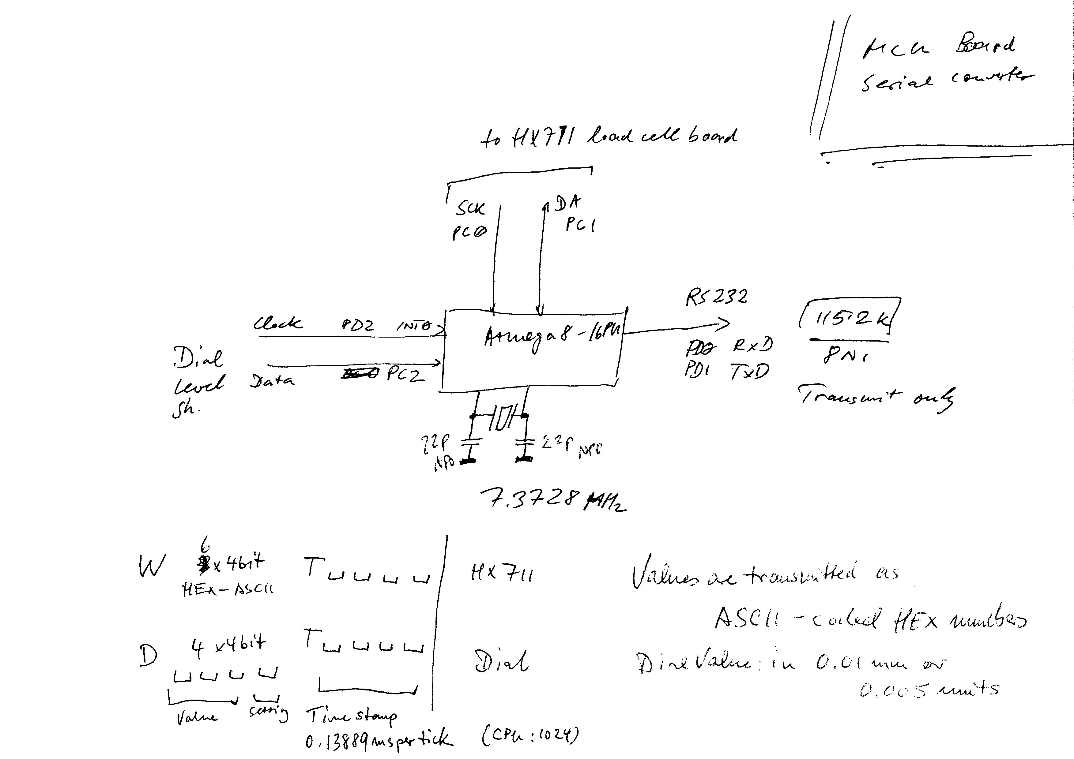
All the data are collected by a ATMEGA8-16PU, and sent to a host PC via a 115.2k RS232 link. This allows even wireless connections, with a serial-to-RS232 converter. Data are send in one direction only, from the ATMEGA8 to the PC. All measurements have a 16 bit time stamp, using the ATMEGA8 16 bit timer.

The 8 bit timer of the ATMEGA8 is used to capture the data from the micrometer, which uses a synchronous clock to transmit data – the risking edge of the clock will trigger an interrupt, INT0, and the timer will ensure that each data Frame is received properly (the timer will overflow after each received data package, to signal that the next clock edge will be the start of a new data package).

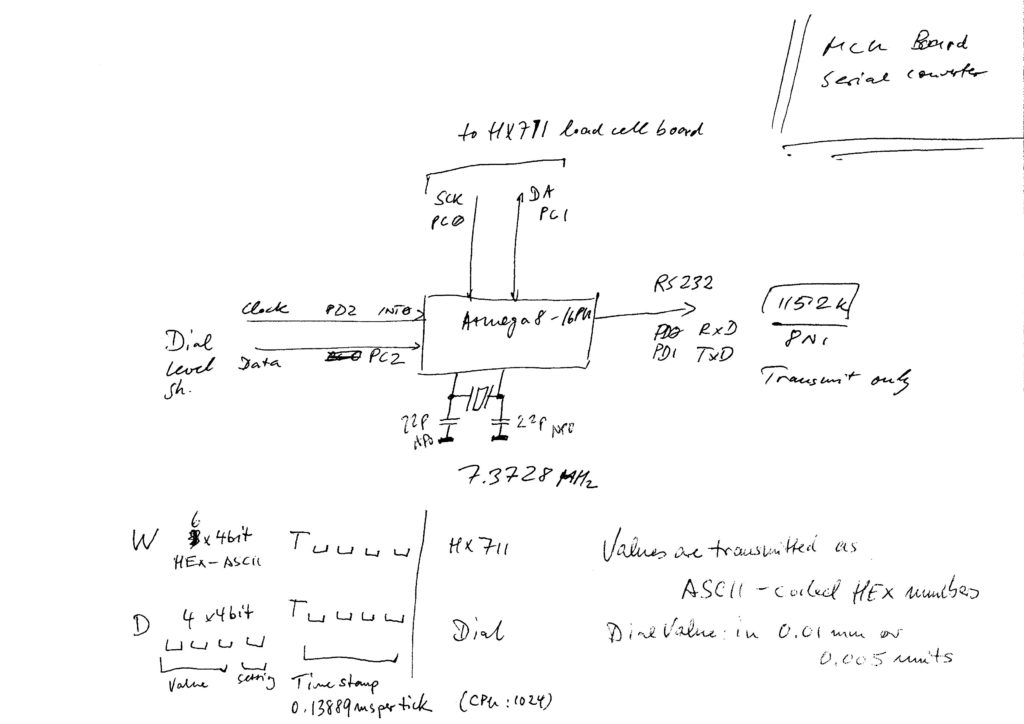
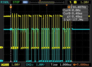
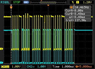
The dial transmission pattern: one data block is send every ~100 ms.

Some detail of the timing, for the current dial indicator interface, data are valid at the rising edge of the clock.

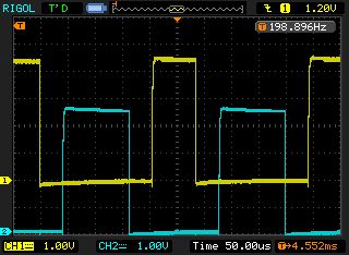
For the last bit, there is no falling edge of the clock.

For “0” logic state, the dial interface pulls down the data line for each clock pulse, and then releases it again for high. Not sure why that is, maybe it saves some battery power?

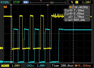
The data is transmitted as binary number, 24 bit, 0.01 mm or 0.005″ per count. The last 4 bits are uses for status and indicate a “-” display, and mm vs. inch.

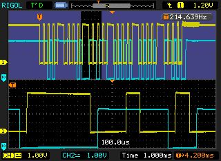
That’s the full pattern of a transmission sequence from the HX711. Blue is data, yellow is clock.

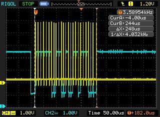
Timing – data line changes states quickly after the rising edge of the clock signal.

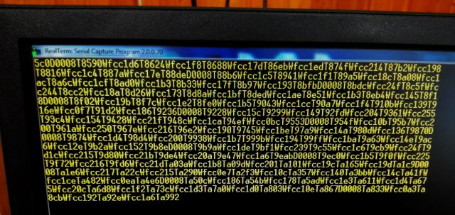
This is the final data stream as received. Notice the time-stamped load cell and dial transmissions.

For those interested, here is the MCU code (AVG-GCC): loadc_d0.c

Jansjö Reading Light Conversion: running on 12 V, and never running out of light again, even in remote places!

How any would it be to have nice reading light at the garden house (or in the car), especially, a light without any smoke and hazard and hazzle like candle light! A light that keeps your eyes healthy. Well, at home, you can just use an IKEA Jansjö light for this purpose, which has a single 3 W LED installed.

All that is needed is a 12 V constant current board, LED driver. These are really cheap, so there is no need to build one yourself, you can just get it shipped from China directly, for a very reasonable price.

This board has a few nice components: 5 SS14 diodes (Schottky), 4 are used a bridge rectifier, 1 is used for the buck converter. There is a 47 Microhenry inductor, a 220 Mikrofarad (25 V) capacitor – and, the magic switch and regulator, a PT4115 device.

The PT4115 features a pretty straightforward design. It’s a step-down converter, can can drive over 1 Amp of current. The board I am using has a 0.22 Ohms current sense resistor, i.e., it is set to 0.1 V/0.22 Ohms = 0.46 A of current. This is plenty to drive the IKEA lamp.

The lamp itself will remain completely unmodified, just using a socket to connect to the original plug (which used to plug into a mains-powered LED driver of similar current rating). The connection to the 12 V system of the garden house is done via a “cigarette lighter” plug.

To protect the driver board, all sealed up in hot glue! It’s not perfect, but it works!

Finally, not much more to say, it works just fine!

SME Tonearm Series V: a really THIN wire!

A rare guest in my workshop, a high class “SME Series V” tonearm, a great item for the audiophile! Unfortunately, the arm we are dealing with is not working – easily traces the issue to a broken wire. Wait – with the tone arms, you can’t just pull out the old wire and put in some odd wire – it needs to be 0.0127 mm2 seven-strand silver wire!

sme tonarm 1

sme wire

After some careful disassembly action, one of the wires was found broken at the needle end, easy enough, soldered it back on, followed by even more gentle and careful re-assembly of the unit.

tonarm wiring

All in all, nothing too difficult, but not an everydays’ task, and it made a friend of mine, the proud owner, happy again!

Solar Upgrade: Another 140 (40?) Watts

Summer is already at its best, but unfortunately, my solar system (of the garden house) is not performing as it should. The battery is never at the predicted state of charge, and somehow, all performance is looking pretty much off the earlier predictions and calculations. Why is that? Well, first, checked the charge controller, but all seems fine. Next, the two solar panels (about 100 W each), and to my greatest dissatisfaction, one of the modules is only giving 8 Volts, rather than about 16-18 Volts, in full sun, and with no load connected. That’s not good.

A few days later, a big, flat box arrived –

dav

– with a 140 Watt polycrystalline solar panel! Quite affordable, just about EUR 115.

dav

Quite beautiful to look at, especially, at the current and power information.

dav

Mounted it on the roof – there is still plenty of space, but one module will be good for now.

dav

Below you can see both the new and old modules. One of old modules (the polycrystalline module) has been disconnected – I will leave it on the roof for now, at least it is shielding it from the rain.

dav

Updated simulation – with an assumed, generous power usage. Seems we should be good even in winter. But let’s find out later this year!

solar simulation

HP 8569A Spectrum Analyzer: A shaky fix

Coming back to an earlier post, 8569A CRT DONOR NEEDED, I was desperately looking for a new CRT for an old 8569A.

After some hints of a kind reader of this blog, I decided to give the box another try, and removed the CRT. There was nothing wrong with the grounding, or the Aquadaq coverage, but at least, there was a sign of defect – a glass chip rattling loose inside the CRT. Turned the CRT with the face to the ground and gave it a few good hits. Reconnected everything (with carefully inserting the CRT back in the box). There result – all working great again. Seems that a piece of glass got stuck in CRT deflection unit, and caused the distortion of the screen. Appears to be a pretty rare defect, but at least, the CRT should be good for now (unless you sit the 8569A on the back feet so that the glas piece can get stuck again in the deflection unit).

Still, some more trouble with this unit:

(1) Rebuild the switch assembly and reference level encoders, about 3 hours of work, and a lot of tiny M1.2 screws, etc.

(2) Some start-up issues: the 8569A would sometimes only start when the “reset” button is pushed. Checked the EPROMs – and, one of them corrupted. Replaced the whole set, just to be sure. These are all TMS2516 EPROMs (let me know if you need the good binary images).

8569a differences

(3) Still more tedious work, replacing the mains filter… many wires… and the mains filter X2 cap.

dav

Now, some quick tests: sensitivity test of all bands, and at 18 GHz, all to specification!

dav

Also checked the power reference, with the best two powder meters at hand, all reading to at least 0.1 dB with no adjustments.

sdr

This repair is done, but please, don’t put this 8569A on its rear feet!

Marantz Stereo Amplifier PM-14 MkII: explosive silicon

A heavy beauty, a Marantz Amplifier, PM-14. Certainly worth a detail look – according to the owner, the left channel is not working, and some smoke escaped along with burned smell.

No wonder – the two main transistors of the left channel are blown, say, exploded. And, upon further inspection, also the traces leading to the transistors, at least some of the traces – evaporated.

bty

This is the full view of the left channel amp (right channel is quite similar, but mirror image – some components placed at slightly different positions.

bty

bty

Some burnt resistors replaced…

bdr

The board is double sided, but not through-plated, and the quality, well, is not all that good – needs to be soldered with care, otherwise the traces will lift.

After some further checks, fitted a new set of transistors (ISC brand, China – still better than some fake “Sanken” transistors), but to the biggest disappointment, when switching on, these exploded in a loud BANG when adjusting the idle current. Well, turns out that also one of the earlier stages had a short transistor 2SA1145. More testing revealed another defect, a dead Zener (exchanged both Zener, to make sure that there are no issues with temperature drifts etc.).

With all these things fixed, time for a test, using a HP 8903A, and a scope. The HP 8903A is really handy, if your are into any quality audio repairs.

The test setup –

nor

Distortion measured at several frequencies, and several volts RMS at the output (using a 5.6 Ohm dummy load – just because I didn’t want to take out the 4 Ohm precision load for these power levels). -80 dB total harmonic distortion+noise, not bad.

bty

bty

bty

The front view – it has the classic Marantz indicator, for best sound, wait until it has warmed up.

bty

nor

As a reference, just in case you need it, the service manual Marantz PM-14 Service Manual. Or, just send me a message, or the come along with your dead amplifier.

HP 8640B Signal Generator: A new divider

The veritable 8640B generator, a marvel of engineering and still remarkable design today, it has reached an age where repair is often hampered by obsolete parts – sure, you can search for a donor unit or some NOS parts in some far away places, but in other cases, it is more practical to replace the circuitry with some new parts, especially, if the circuit is easily tested and verified.

This applies to the pre-scaler/frequency counter, which is an essential part of the 8640B, at least, if you want to use its internal counter (the 8640B is not PLL controlled).

Thanks to a kind contributor, Bodo, here a brief story of the repair:

(1) Symptom: the 8640B showed irregular frequency counts, completely unrelated to the expected output frequency. First consideration was a defective band switch (which has a cracked Delrin gear), but test with a spectrum analyzer revealed a perfectly good signal. Connecting a 0-10 MHz signal to the external counter input also gave perfectly good counting.

(2) After study of the schematic, the issue could be traced to the RF scaler, which is located in a die-cast cavity. Note that there are various versions of this board, but all feature some ECL logic ICs, with high power consumption.

prescaler 8640b assemblly

(3) Further tests showed that the first divider, :2 was defective.

(4) There are several ways to fix this. Here, the complete divider chain was replaced by a U644BS, available in DIP8. This IC is quite common in old TV tuners. There were also several projects in popular electronics magazines of the 90s to use the U664 as a pre-scaler up to 1.3 GHz.

Datasheet U664B U664BS

Picture of a random tuner from the web, using a U664B:
prescaler tuner

With the external input, the 8640B is counting up to 900MHz, sensitivity is better than -25dBm.

Note that the U866BS is self-oscillating (not a problem, because the 8640B oscillator is permanently attached for internal counting).

The modified prescaler board under test:

prescaler 8640b u664bs under test

One side effect is the much lower temperature of the RF scaler (much lower power consumption of the U664BS vs. the old ECL logic).

Finally, this is the schematic, the signal is connected from a-INPUT to b-OUTPUT.

prescaler 8640b schematic

HP 8569A Spectrum Analyzer: Any organ (ehh, CRT) donors out there

This 8569A came from the US, purchased by a local HAM operator, and in need of repair. Some switches don’t move nicely, so it seems liked a regular repair job of a 8569A.

First issue, 5 minutes after turn-on, where not the switches, but a blown mains capacitor (aging X2 grade capacitor). Well, this is easy to fix.

With the instrument powered on, it quickly became evident that the there is some distortion of the display, in particular, in the upper section of the CRT. This is not a common fault, and hard to explain other than by a broken deflection system of the CRT.

To be absolutely sure that no other assemblies are causing this defect, the X-Y deflection signals were coupled to a working 8569A, and indeed, no distortion visible.

The CRT display of a working 8569A – with the X-Y signals of routed from the unit that shows the distortions:

Sure, the display is not quite synced (also because of the extension leads with alligator clips). How to proceed? Well, this will need a 8569A CRT for repair, from a donor unit. Let’s hope, at least for the HAM friend that one will come around soon.

Workshop upgrade: Light fittings, and luminous efficacies

With the workshop basic repairs complete, how to set up a cost-effective lighting system?

Some items to consider
-I will be working there mostly after work, late in the evening, and mostly in the dark winter months. So I need daylight and bright light to keep focus.
-Diffuse light along will not be enough. I like the feeling of incandescent lights, so there need to be some work and bright direct lights.
-Some areas, like the stair, will need a separate light, which needs to be “ON” immediately after the switch is pushed. Same applies to the other lights – there should be no dimm start-up, flicker, or start-up delay.
-Light level needs to be high, because the main purpose of this room is the assemble, fix, and test high frequency/microwave assemblies, and fine-mechanical devices.
-Because this is a hobby, we need to keep expenses down, both for the initial cost (light fitting and lamps), and the running cost – electric power cost.

This is a plan of the room layout, rectangles mark the position of tables.

Essentially, two kinds of light sources have been considered – T8 fluorescent, for the background illumination, 8 pcs. 25200 lm total (EUR 5 per piece, including lamp and electronic started – a bargain). And 4 PAR38 30° LED down-spots (these replace the 108 W halogen lights, and have still have a nice glass body).

licht parathom

These are about EUR 13 per piece, and the light fittings are simple screw sockets E27 size, EUR 1.50 per piece.

licht raumplan

Some calculations done – total of 31 kilo-lm, 363 Watts (which is quite precisely found when checking the total current to the workshop with a wattmeter). ~85 Lumen per Watt, which is a very good value.

We will need to check the actual luminous intensity at the work surfaces later, because the lumens of the fluorescent tubes is not all going downwards (some reflected from the white ceiling and walls, some lost in the light fitting).

licht efficiacy

Life time these lights are rated for 25000 hours (LED), or 12000 hours (T8 tubes). This means, 3000~6000 hobby days (counted at 4 hours), so there should be no need to change these light bulbs and tubes any time soon.

SimonsDialogs – A wild collection of random thoughts, observations and learnings. Presented by Simon.