HP 8566B Spectrum Analyzer: A19 board, YTO unlock, bad precision trimmer(s)

Not the first HP 8566B on the bench, and not the first at all showing the famous “YTO unlock” message. Most of these YTO unlock message issues can be traced to defective capacitors, but not this time.

With the 8566B, take my advise, don’t touch any of the assemblies if you aren’t really sure which one is at fault, it is a fairly complex machine. To troubleshoot, a microwave counter is handy, to check the LO frequency.

8566b-repair

Next, the PLL was disengaged by disconnecting the cable from the sampler/LO pll. Still, no good LO frequency output. This leaves two main assemblies to be checked, the LO pretune DAC, and the YTO driver assembly, A19 and A20, respectively.

Quickly traced the issue to the A19 DAC assembly, and luckily enough, had a spare one around, albeit, an older version. After swapping the boards, it was confirmed that the A19 assembly is really the faulty part.

8566b-085660-60164-a19-brd

8566b-085660-60212-a19-brd-old-version

Next – desoldered all the capacitors at one end, but, to my surprise, all useless work, all caps in best working order, even after 25+ years!
Checked various components, and finally, found some issue with the precision trimmers – seems a cold or aged solder joint. To be sure the the fix is as permanent as possible, all the trimmers were removed, the solder connections cleaned, and all installed back in. Easy fix, all working again.

With this unit, there was no intention to do a full calibration, but as an extra service, I checked the power at the reference signal outlet – see below. Quite amazing how accurate, and pretty sure that this unit hadn’t been at a cal lab for at least 15 years….. this is really a superb level of lasting precision and quality, and ingenious engineering.

8566b-pwr-ref-test

Avantek S081-0321 YIG oscillator: not oscillating at all

One of the best sources of microwave signals still are YIG oscillators/YTO. These do require a good amount of power, magnetic coils, etc, but provide stable and rather low noise output, and good modulation capability. Core element is a small YIG sphere, placed in a magnetic field.

However, for the current unit under investigation (from a 18-26 GHz frontend), type S081-0321, 8.0-13.4 GHz, all the magnetic field and effort is wasted – no output detectable at all, not even a faint signal (checked with various equipment). Knocking it with a (small!) hammer, no effect. Varying the coil current – no effect.
Current consumption on the 15 V rail is normal.

yig-test-no-signal

yig-s081-0321-defective

Well, with all the basics checked, what to do with such hermetically sealed unit, other than using it to satisfy my curiosity about its internals. Hope to trace the defect to some specific part.

But before we consider more destructive measures, let’s try to re-tune the YIG by slightly adjusting the YIG sphere. This is possibly throught the side opening, which is usually welded shut, but can be drilled up rather easily.

yig-adjustment-open

Still no luck, no signal, even after turning the YIG quite a bit.

To look inside, carefully removed the top weld seam on a lathe, and the you can pry the case open.

yig-osc1

What you can see is pretty straightforward, despite all the gold wires. There is an input voltage regulator, from +15 V rail, down to 8 volts (measured about 8.15 V), this is then distributed to the 4 active parts via resistors (the bluish elements). Voltage at the resistors is about 4.3 V, so all stages seem to be adequately powered and current flowing as usual. Still no signal. Also probed other parts of the circuit, with a thin wire, under the microscope. No obvious defect. The gold wires and contact point reveal a good amount of adjustment done by placing/removing bond wires as need to adjust bias currents, probably also frequency response, etc.

yig-osc-closeup

The coil – rather, the coils. The thick wire is the main tuning coil, which accepts 0.4~0.6 Amps, the small coil around the magnetic center pole is the FM modulation coil. This is for much lower currently but high bandwidth modulation. All is sealed and soaked with epoxy resin. Note the hand made labels which may explain the cost of these units if purchased new… looks like US style handwriting to me.

yig-internals-mag-coil

Well, seems that fixing this is beyond what I can do here with the tools at hand. So will need to look for a spare/used 8-13.4 GHz YIG/YTO somewhere.

EIP 545A Microwave Frequency Counter: another dead tantalum repair

It’s not the first fix of an EIP counter here, and I have to say, these units are still very useful tools around any RF and microwave workshop, despite their age. The unit under repair, judging from the date code of the parts, is about 25 years old.

The symptoms – the EIP is just not counting. Showing 000000 zeros in the display, but no count. To confirm, you can use the build-in test function 01, by pushing test-0-1, and normally the counter will show “200 000 000”. But no indication of any counting activity for the current unit.

First thing you do, checked all the rails, and turns out the 12 V rail is dead. Starting from the right, removed all boards inside. And soon the defect was traced to the A107 board, gate generator assy.

Checking with the schematic, there are several ceramic and one tantalum cap.

eip-cap-desoldered

Desoldered the tantalum, and it is no cap any more, just a short.
With all the various tantalum shorts repaired in the past years, there seem to be to cases, some tantalum go fully short and activate the power supply protection circuit, with little powder dissipated over the tantalum. This is the good case. Some other tantalum seem to develop a short with some resistance, leading to considerable power dissipated in the cap, causing stench and risk of fire. The latter more seems to be more common with SMD tantalums, for reasons unknown. Also, the tantalum story is one of the many reasons why you should design current limit circuits, and power supply protection circuits, even in low power equipment, especially, if there are any valuable components that you might want to protect from a power supply failure.

eip-cap-a107-gate-gen-assy

eip-cap-replaced

The 10 uF replaced, with a new orange cap, but same “drop” style.

eip-counting-again

After carefully installing the A107 assy back into the counter (take care not the damage any of the wires), all is good. Counting at 200 MHz with the test function 01 activated.

A precision pendulum clock, and an even more precise time interval counter

Several years ago, I managed to get hold of a rather special piece, an electromechanical master clock, including an Invar temperature compensated precision pendulum. Such clocks were use to control various remote clocks at a train station, in large factories, or huge governmental offices, etc.

These clocks have long been superseeded by crystal oscillators, nevertheless, they are marvelous pieces of precision engineering, and it has been a long held thought of mine to measure how accurately this time-piece is performing, not only long-term (which can be easily timed by daily checks), but also short time, for each individual tic.

The pendulum has a 1/2 period of 0.75 seconds, which is quite common for such kinds of electromechanical clocks. Only the most wealthy businesses opted for a 1 m (full) pendulum, and the instrument is large enough anyway even with 3/4 lenght.

eclk-full-view

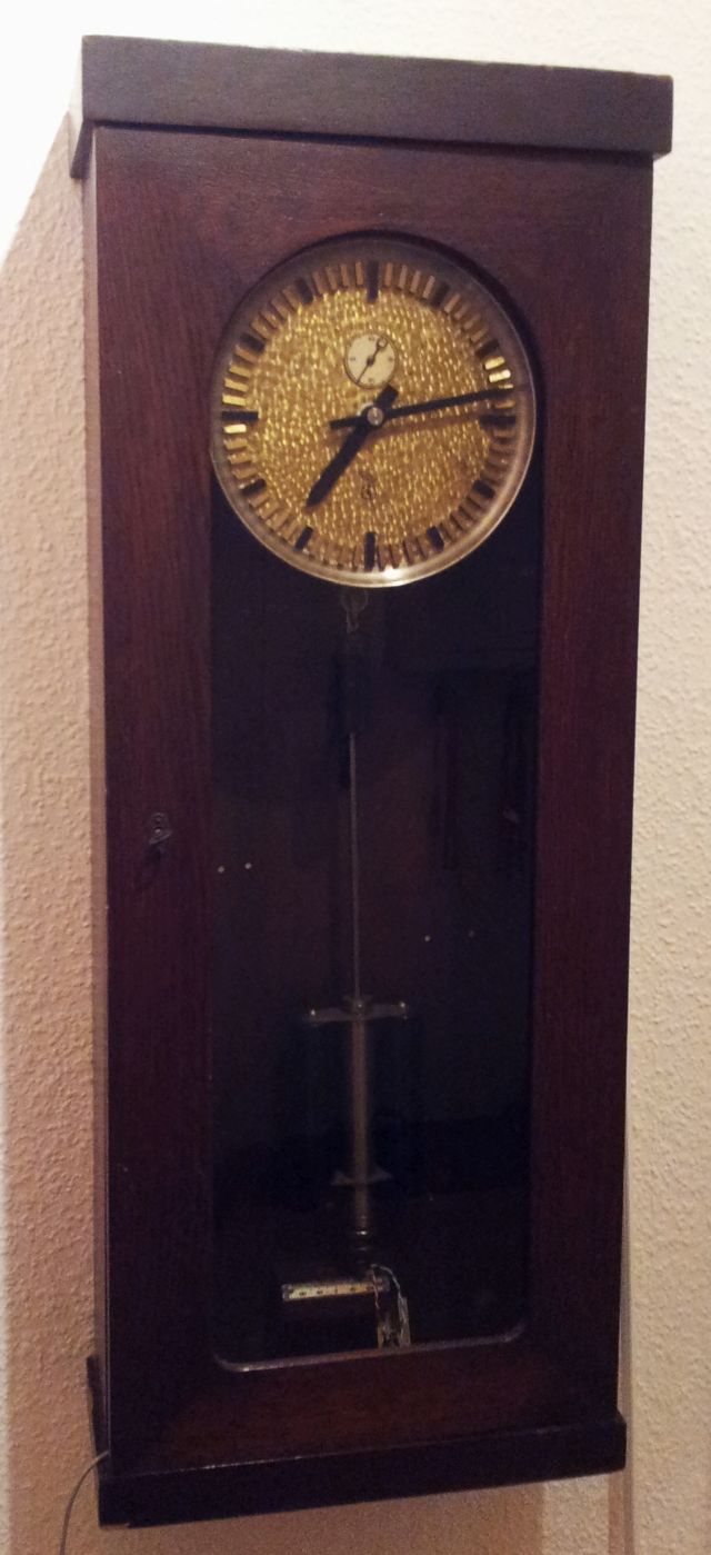
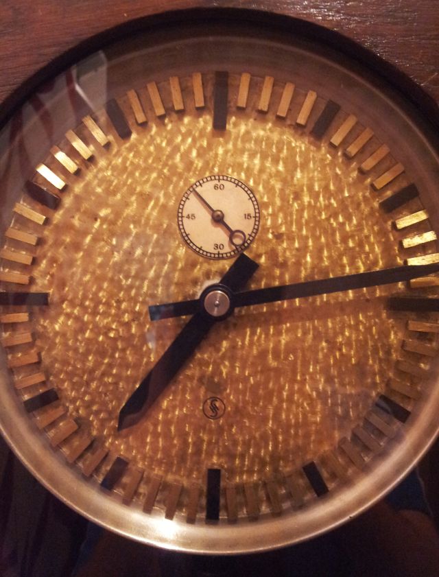
The dial is quite beautiful, and every piece appears to be hand-made. There is no date on the clock, but the age of the capacitor suggests 1920~1930 time-frame. I fully rebuild the mechanics about 3 years ago, all degreased, checked, and freshly lubricated with clock oil. There was no need for any other repair, all parts and bearings are still in good shape.

eclk-dial

The clock has a rewind mechanism that is activated once per minute, and also turns a polarity reversal switch, used to steer the remote clocks.

eclk-pickup

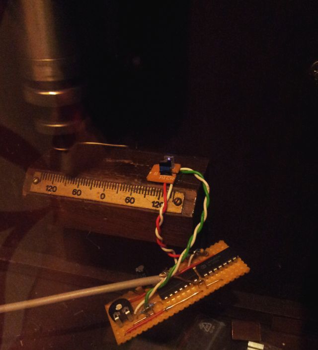
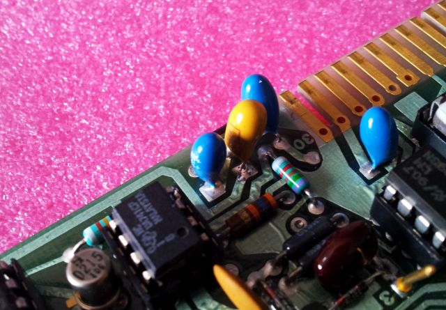
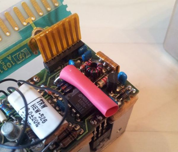
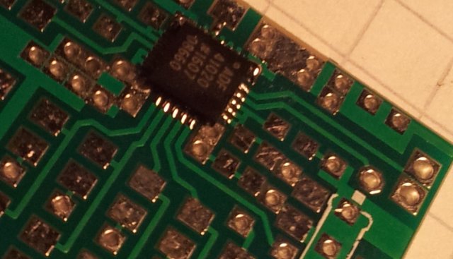
To get the signal out of the clock, a small light gate has been setup inside, and a 1 mm wire connected to the lower end of the pendulum (in a way to ensure virtually no movement of the wire). The wire interrupts the light gate approximate at the lowest point of the pendulum, i.e., when it has its highest speed – this is to ensure sharp edges of the signal.

eclk-setup

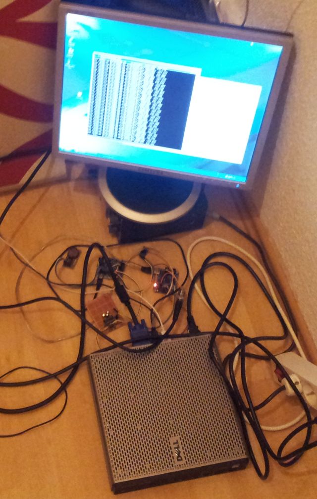
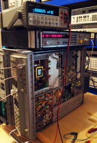
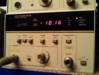
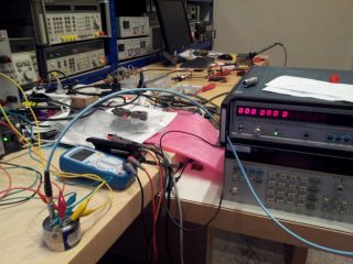
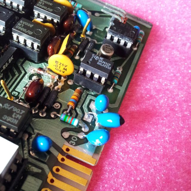
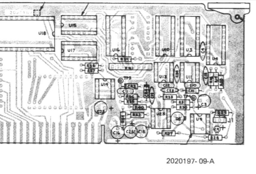
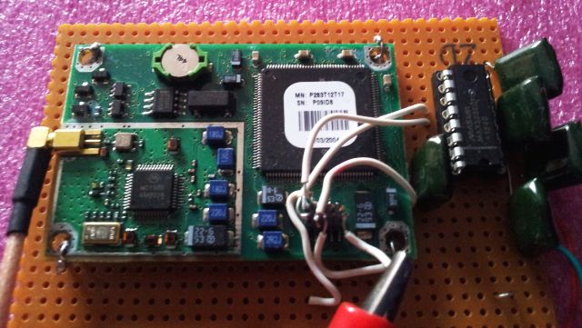
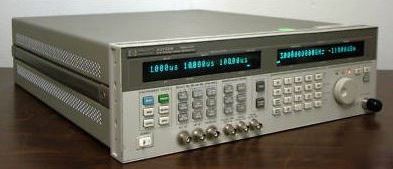
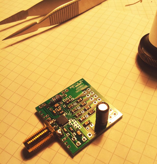
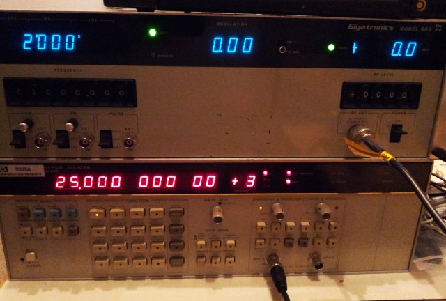
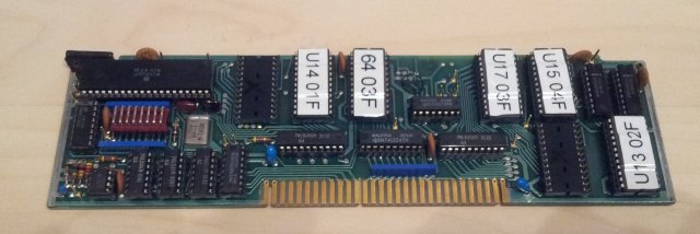
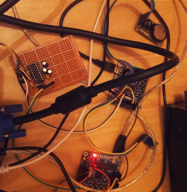
The setup, currently it is just a set of boards running the TIC4 and LOGGER5 software discussed earlier. A Dell OptiPlex FX160 is used to collect the data, but you can use any kind of computer that can handle RS232 input.

eclk-boards

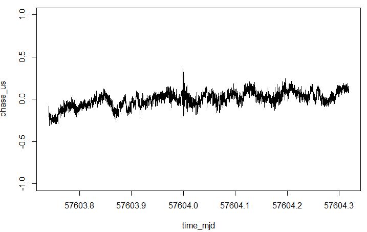
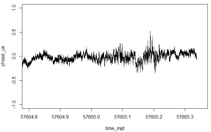
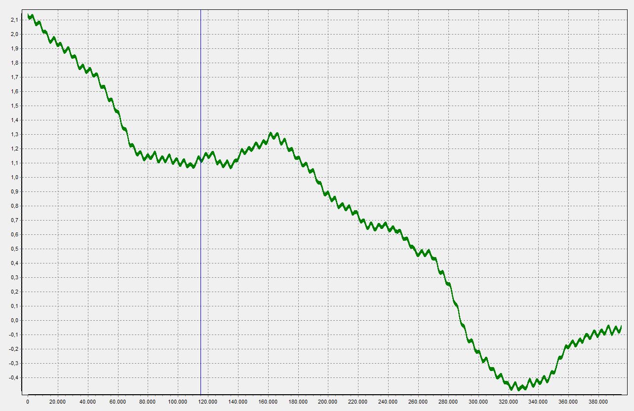
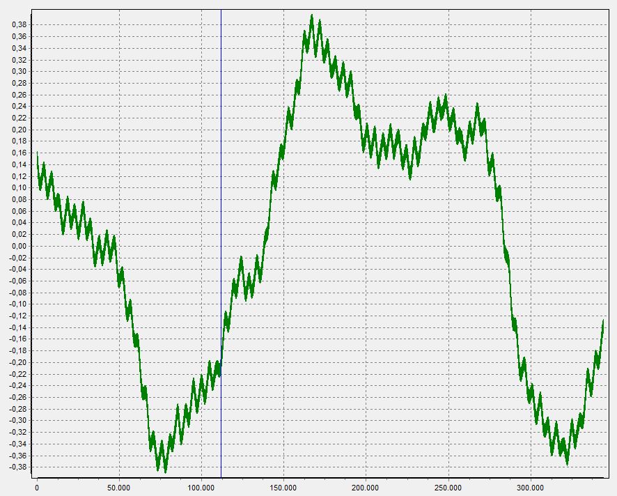
Here, some first results – more to come. Phase is given in seconds, and horizontal axis shows the tick counts – about 115k ticks per day. The software uses narrow time gating to sort out any incorrect ticks, caused by electrical interference, or other random disturbances. There are no more than 1-2 of such events every day. The phase reconstruction algorithm also handles any missing ticks, and the measurement accuracy is not compromised if one or more tick events are not registered for any random reason.

eclk-phase-drift

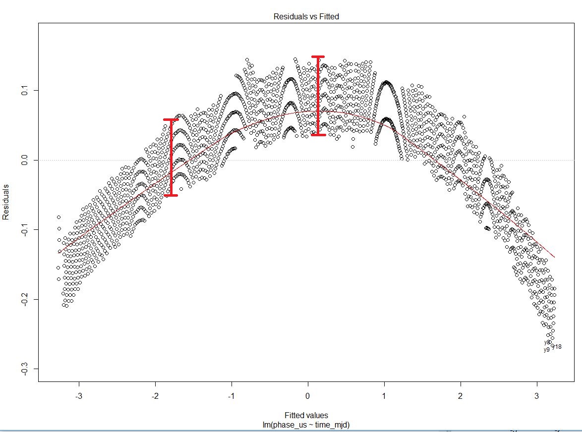
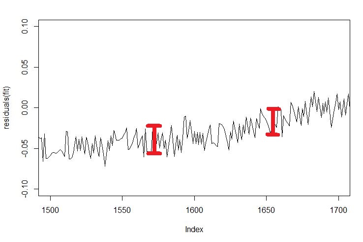
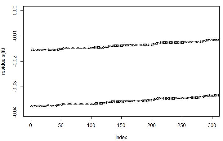
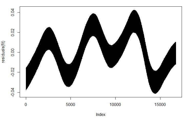
Removing the linear part – not a lot of residual phase error left. Plus minus a fraction of a second a day. Now I have slightly slowed down the clock by removing a tuning weight from the pendulum.

eclk-drift-removed-residuals

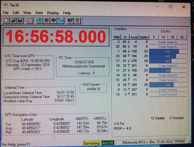
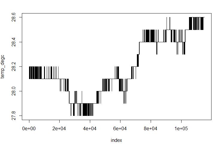
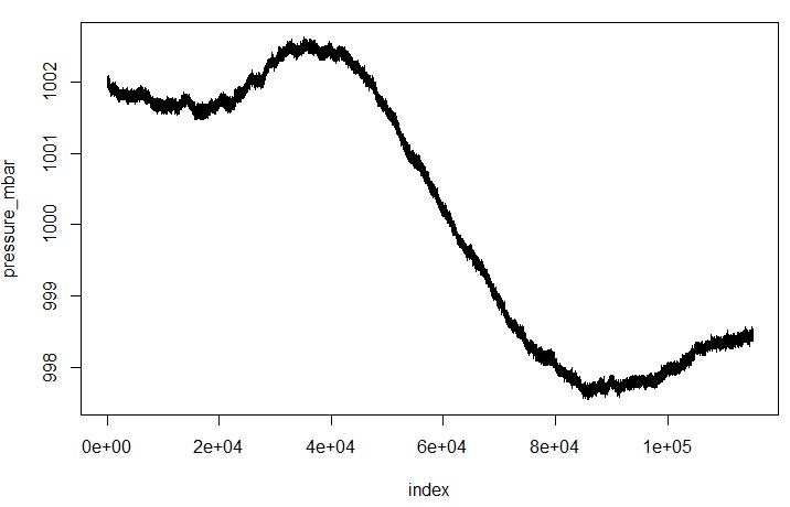
As described earlier, the LOGGER5 setup also records real-time (not to a high degree of precision, just to keep track of time and day), and temperature/pressure. See earler post, LOGGER5, and TIC4.

eclk-temp

eclk-pressure

Below, and interesting feature of the data – with the re-loading of the clock every minute, there is some slight variation of the frequency. It is really not much considerable the notable “CLICK” with every re-wind, done by a large magnetic coil, actuating a lever mechanism.

minute-variation

The hourly variation, most likely, related to the travel of the minute hand – will check this later, simply by removing the hands!

hourly-variation

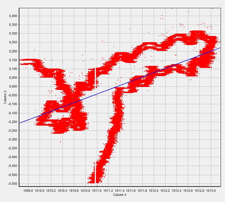
Some first correlation of frequency vs. pressure, but will need to collect much more data, and then correlate with pressure and temperature.

phase-res-vs-pressure

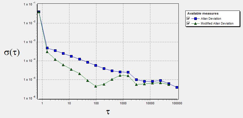
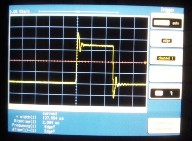
Finally, the Allan variation of the clock, determined from a few days worth of data. Short term stability is compromised by the bi-directional pick-up of the pendulum (detection is at the rising edge of the pulse, which corresponds to two different positions of the pendulum relative to the light gate – because of the discrete thickness of the wire).

eclk-allan

Perfect time: upgrade to a Motorola M12+ receiver, and new GPS antenna

For years, a Motorola UT+ GPS timing receiver has served me well as a frequency reference and source of accurate time (and location). While I primarily use a DCF77 locked 10 MHz OCXO, the GPS time is useful for various purposes, be it, to confirm that DCF77 is actually delivering the proper time.

One drawback of the Motorola UT+ is the rather large “sawtooth” error, which is caused by the quantization of the 1 pps signal derived from a 9.54 MHz clock. This results in a +-52 phase inaccuracy – which can be corrected, but only with further effort.

The later model, which is dated by now and available at low cost, the Motorola M12+, is much better in this respect, featuring a +-13 ns sawtooth, which is not a lot, and good enough for most purposes without any further corrections.

Below, some tests on an OCXO vs. GPS 1 pps pulses, for a OCXO under test (10 MHz, divided down to 100 kHz, and phase displayed in microseconds).

ocxo-vs-ut

ocxo-vs-m12-100ns

This is the small board, not a thing of beauty, but working. The only parts needed are +3.0 V and +5 V (actually using +4.4 V) voltage regulators: 3.0 V for the M12+, 4.4 V for the GPS antenna.
The 3.0 V also powders a MAX3232 TTL to RS232 converter.

m12plus-board

Also procured a second-hand GPS timing antenna – this one has a nice radome, a quadrifilar helix element, and a 26 dB amplifier to compensate any cable losses. The cable, LMR-195, features N to SMA connectors, and a considerable of PVC tape was used to protect the N-connector from the elements. Still it would be better to use some special outdoor N connectors, but, sorry, don’t have.

m12plus-antenna

m12plus-tac

A handy program to control the GPS – TAC32. Usual procedure is to carry out a location survey, which will take about 2-3 hours, and then continue in position hold/timing mode.

One drawback of my location – there is no way to get full 360 deg view, so reception is limited to the more southern satellites. But usually 6-8 satellites are in sight.

Still contemplating if it is worthwhile to put this in a larger box, together with a 10 MHz OCXO, and possibly a DS1023-50 delay line to implement a hardware sawtooth correction. Maybe a good project for winter time.

A Thermal Fuse, and HP 10811-60111 Repair

Usually, I don’t care much about high precision oscillator options being fitted to frequency counters, etc., because in the lab, any critical equipment is anyway connected to an external well-controlled 10 MHz reference, locked to DCF77. However, this time I need to install a OCXO (HP 10811) in a HP 5335A counter for service outside of the lab.

The only thing that needs to be done is to remove a jumper on the board of the 5335A (see red box in picture below), and mount the 10811 in the slot already prepared for the OCXO inside.

ocxo 5335a jumper

While such installation is fairly straightforward, it turned out to take more time than expected – simply because of the OCXO not showing any stable output signal.

ocxo 10811-60111

After a few quick tests, the cuprit was found, a defective (open) thermal fuse. This is apparently a quite common issue for the 10811 oscillators, and you might get away with just putting in a wire jumper. However, I didn’t want to take any risk of overheating in case of a failure of the 25+ years old OCXO circuits. An exact match for the thermal fuse could not be found, so just soldered in (very carefully, cooling the case and leads!) a 10 Amp 109 degC fuse.

ocxo fuse picture

This is the OCXO with the new fuse installed.

ocxo new thermal fuse

This style of fuse as a non-insulated outer shell, so a shrink tubing sleve serves as insulation.

ocxo insul sleve

Finally, a note found in a datasheet of a common thermal fuse – it clearly states that lifetime will be limited when operating the fuse to close to the cut-off temperature. So clearly, thermal fuses are not the best protective mechanism for the OCXO case. Maybe better would be a bimetallic switch (self-resetting, but at least no subject to any significant aging), or some other device like a PTC.

Sure, we can slightly blame the HP engineers, because it is stated on most thermal fuse datasheets, like the one below, that the operation temp limit should be about 30 degC less than the cut-off, which is not quite the case for the 10811 OCXO. 80 to 84 deg C operation, 109 degC fuse cut-off.

ocxo storage temp

ocxo thermal fuse

DCF77 vs. GPS time comparison: not a lot of uncertainty…

Some folks were asking about the accuracy of the DCF77 10 MHz standard described earlier, DCF77 10 MHz – which has an Piezo brand OCXO, steered by a long-time-constant PLL locked to the DCF77 77.5 kHz carrier.

But, how to assess the short and long term stability of such a ‘standard’ in practical terms? Well, short term accuracy – it will simply be that of the Piezo OCXO, and some noise injected by the power supply. Mid- and long term, the drift will be determined by the DCF77 master clock (which is dead accurate), and the propagation conditions of the long wave signal (which is by far worse).

With my location at Ludwigshafen, Germany, I’m reasonably close to the DCF77 transmitter – maybe 70 miles? So there is hope that the transmission induced effects are not all that bad.

To measure the mid and long term stability, see below two plots of the DCF77-locked phase of the Piezo OCXO, vs. the instantaneous phase of GPS, stable to 40 ns or better, and obtained from a Motorola M12+ timing receiver. Measurements were done by measuring the time interval from the GPS 1 PPS signal, to the rising edge of a 10 kHz signal – derived from the 10 MHz OCXO by a good divider (using a ADF41020 REF input – R divider routed to MUX output) by HP 5335A counter.

dcf dcf vs gps time day 57603

dcf dcf vs gps time day 57604

In short – DCF77 is tracking GPS extremely well, and the OCXO phase is stable to within a few 10 to 100 ns. In practical terms, 1 second of observation time would be well enough to calibrate any frequency standard to 1 ppm or better, by comparison with the DCF77 locked OCXO. In other words, the DCF77 locked OCXO instability appears to be dominated by the propagation of the DCF77 signal more then anything else.

ADF41020 18 GHz PLL: universal divider and PLL board

I cannot praise Analog Devices enough for the ingenious designs, and for providing parts like the ADF41020, a fully integrated 18 GHz PLL. This is actually part of a major design effort for a multi-channel frontend, here just a description of the small test board used to establish the general circuit layout and board design.

Probably interesting is also the hand-soldering of the LFCSP leadframe package, which is actually not as difficult as it seems. For soldering of the pad, there is a large via in the center, which does provide good heat-sinking and is easy to solder through the 1.2 mm board.

pll18d0 layout

Above, the layout, below, 10 boards – 14 dollars and a few weeks later.

pll18d0 pcbs

For soldering, best use 0.5 mm Ag-containing SMD solder, with Type 32 flux, which is halogen free resin flux.

pll18d0 solder

To mount the LFCSP, first apply some solder to the chip pads, but not to the center/heat sink pad. Apply some flux to the board (which is already pre-tinned; use any good SMD flux pen). Then align with a good magnifier, using some Kapton tape to hold the chip in place – leave one side exposed. Then solder, in one stroke, using a medium hot soldering tip. Reflow another time – one side done. Remove the Kapton tape, and solder the remaining 3 sides. Then stick down the chip with Kapton tape again (to avoid any remote chance of movement, in case all the solder melts during the next step). Turn around the boards, and solder through the via, with a fine solder tip.

pll18d0 via

pll18d0 adf41020 mounted

pll18d0 full board

For a test, just apply a test signal to the input, and use the “MUX” output to check for any pulses. There we go:

pll18d0 2215 pulses

These pulses aren’t quite long, so it is one of the few occasions where a scope more advanced than the 2215 Tektronix is really useful in the home shop… same pulses on a HP/Agilent/Keysight 54720A, 54713B plug-in, and 100 MHz 1:10 probe.

pll18d0 pulse out

These fast risetime pulses, and the various prescalers, dividers and good input sensitivity make the ADF41020 quite useful for any PLL and frequency counting applications.

pll18d0 2ghz in 25 khz out

2 GHz in, 25 kHz out — confirmed.

About the input sensitivity: the ADF41020 is specified over a 4 to 18 GHz range – how about lower frequencies? A quick look at the input circuit shows a 3 pF capacitor – which equals a reactance of about 53 Ohms, at 1 GHz (i.e., the capacitor and termination resistor will cut the input power available to the buffer approximately in half).

pll18d0 rf input

pll18d0 input sens

… quite useful down to 1 GHz, no problem or instability at all. Also checked the the reproducibility, for 3 devices – not a lot of scatter.

EIP 545A Microwave Counter: another power meter upgrade

This is just a brief update on an earlier post, related to the power meter option for EIP counters, EIP Power Meter Upgrade. The current 545A came without any options, even without GPIB, and I was not quite sure if the firmware power meter option firmware would work, even if no GPIB option is present. Well, easy enough, put it to test.

545a upgrade eproms

It didn’t take much, a few (rather old 2516, and 2532) EPROMs, a resistor, some spare ICs, and a few inches of solder…

545a board

Here, the result: all working just fine, counting away at several GHz, and power reading appears to be resonably accurate. I would not substitute it for a proper power meter, for calibration purposes, but the power meter option is a handy feature for any quick test and confirmation.

545a upgrade test

SimonsDialogs – A wild collection of random thoughts, observations and learnings. Presented by Simon.