Wavetek 172B Signal Generator: a heavy 00000000

This Wavetek has been part of an Army sale a while back, and I had used it for some project, but in recent years, it started to gather dust – it is a nice units but pretty heavy and I don’t want to hurt my back.
When I switched it on recently, it showed all “0000000”. The keypad is responsive and a beep sounds with any key pressed, but there is no reaction or output. Sure this can be fixed but I am not a Wavetek expert and all hands full with large gardens and other projects. So I sold the Wavetek to Ulrich Prinz DC3AX who kindly fixed it and shared the repair pictures and details below. Also I have the EPROMs archived in the Manuals Archive in case you need it.

Turns out that the keyboard has an independent processor, but the main CPU board is not initializing properly, normally, it needs to send a string “Wavetek 172B” to the display with self test completed, but the CPU doesn’t do anything.

The sockets on these boards are nowhere near Hewlett Packard quality, but single spring low cost IC sockets that are prone to aging and contact issues. The most critical ones around the PROMs were replace with precision contact IC sockets.

M2114 4k static RAMs, these are known to fail at times, so they were replaced.

Finally, a test, and it boots up and runs through the self test no issues. A marvelous repair because CPU boards can be tricky to fix – let’s hope for long and trouble-free service of the unit at its new owner!

New Smart Home: at least, gas&electric meters are talking to the world wide web

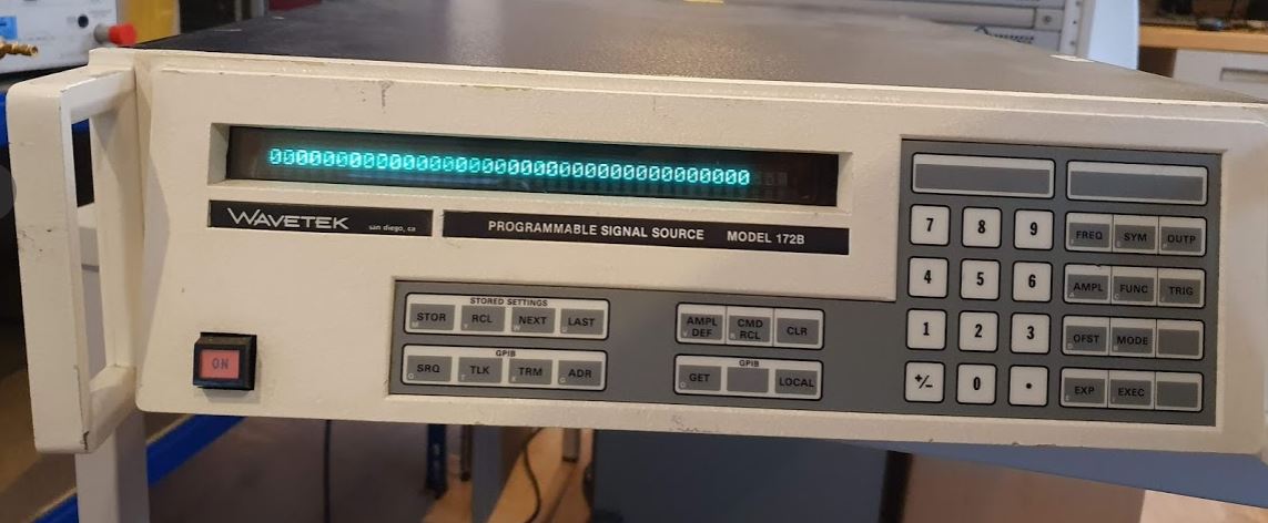
With the recent move to my new home, some curiosity about the consumption of energy, gas and electricity, first and foremost. The heating system is completely new, so there were no historic data about the annual consumption, and with winter time currently, I thought it could be interesting to collect some data and analyze.

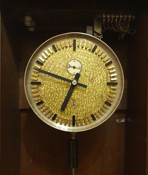
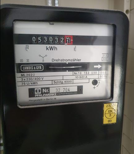
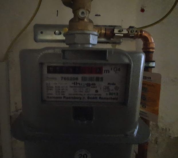
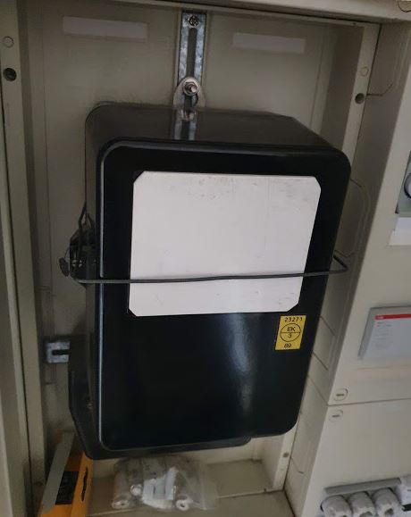
The meters are not the best starting point, the electric meter says, manufactured in Western Berlin, e.g., during the period of separation in Germany, pre 1989… The gas meter is a but more recent but the well known old design.

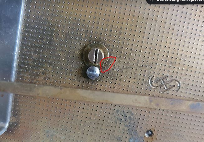
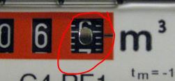
At least, the gas meter has some provisions for digital read-out, probably, a magnetic system, with relatively coarse resolution, and a mirror “6” which aids itself to optical pick-up with 10 Liter resolution.

Here you can see the mirror… the “o” of the “6”.

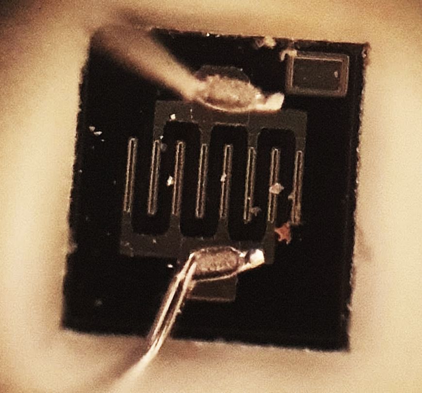
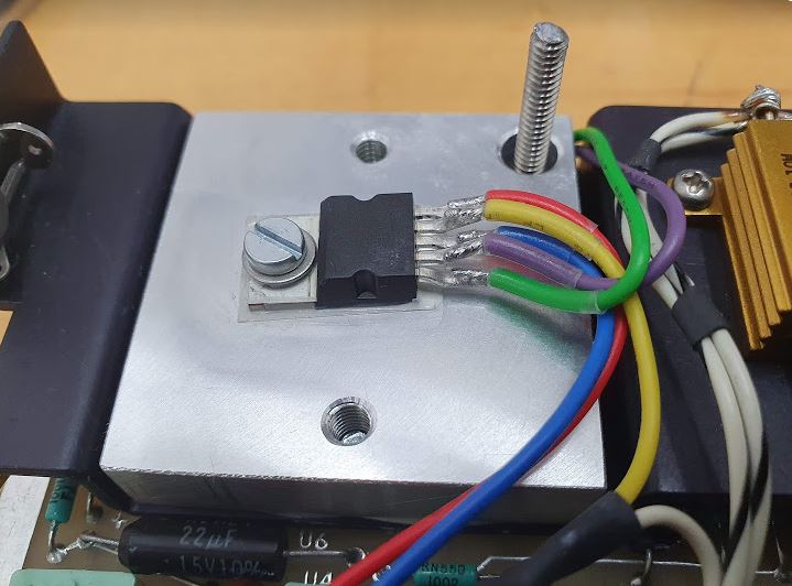
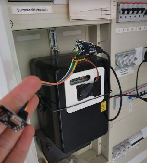
To pick up the reflection, I used some IR transmitter-receiver pairs, you may take similar from an used computer mouse, I purchased some sets as surplus parts years back.

Now, the next challenge is to get the readings of the meters from the basement and 2nd floor, to the ground floor office that has the web server – to collect the data in one place and to analyze.
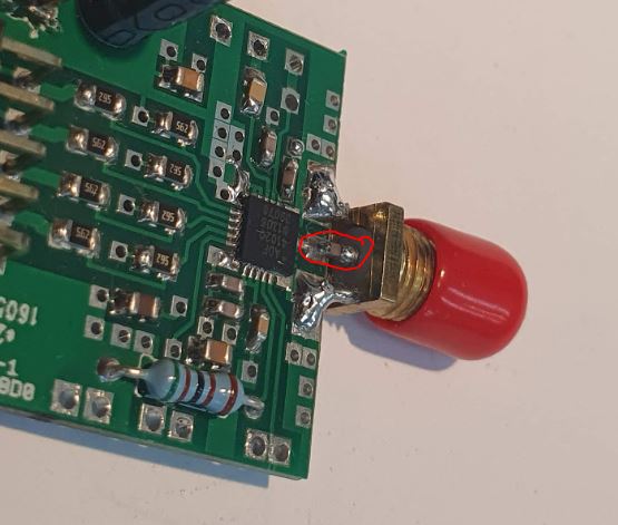
This is achieved by NRL24L10 transmitters in the 2.4 GHz band. These transmit to a common receiver that is connected to the web server (running Apache/Ubuntu) via a wired 9.6 kbaud RS232 link.

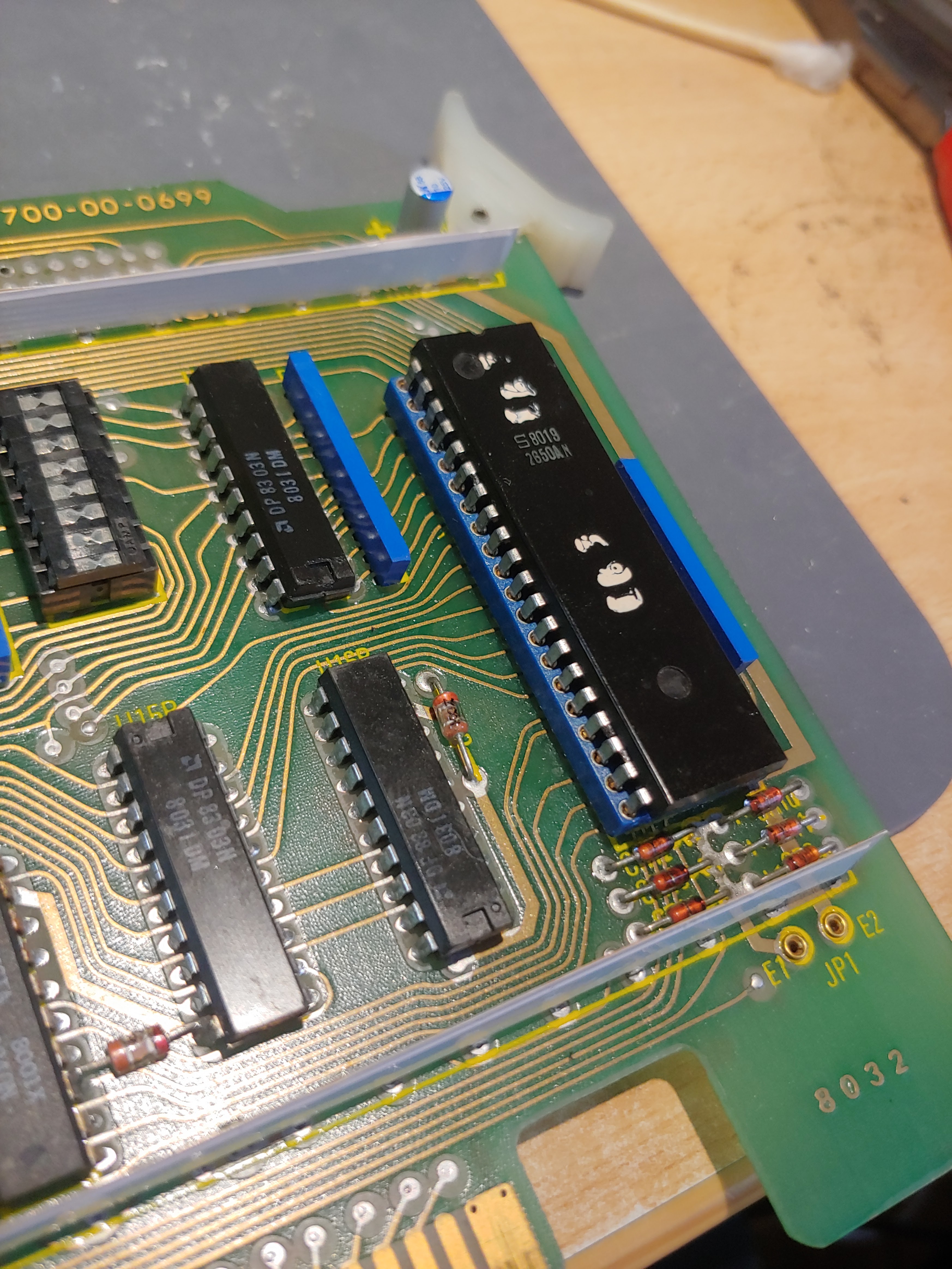
The transmitters and receiver are controlled by Atmel m328p, from some ready-to-use Chinese controller boards similar to Arduino nano, but the software and use is all avr-gcc, nothing to do with Arduino.

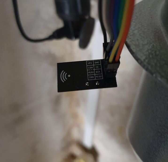
There is no need to deal with the NRL24L10 chip itself, because there are ready-made small boards available cheaply, less than 1 EUR per piece…

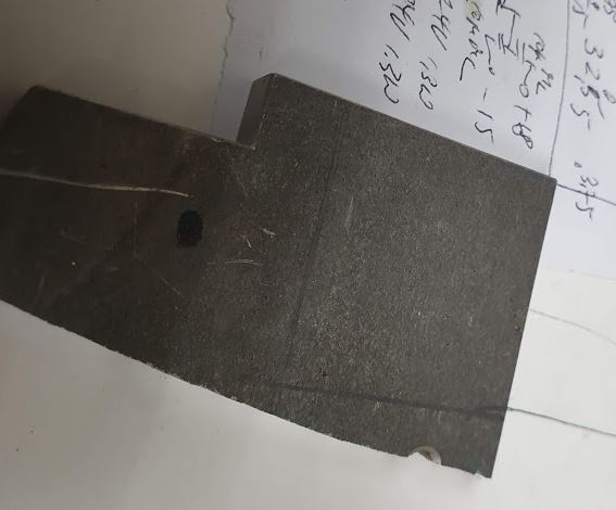
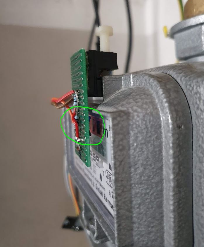
For the gas meter mechanical part, a small piece of plastic scrap and a Nylon screw is all that was needed to get a stable signal.

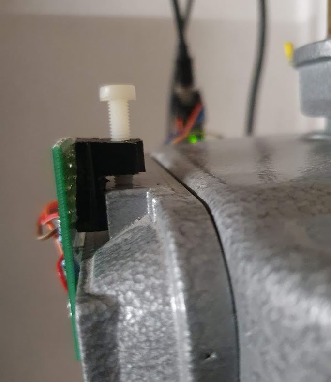
Sure it needs to be positioned well, but it is not a particularly sensitive or critical adjustment.

First, I just transmitted the strength of the reflected light to the server (receiver), and did all the calculation in the receiver, but this has various issues if the transmission of the signal is interrupted for some reasons, like RF interference or some other outage at the receiver end.

So I decided to change to counting the “6” pulses at the transmitter end, and the transmitter will send data every few seconds (including the time stamp of last counter change, and a time stamp synchronization data package every 10s of seconds).

Now it is counting very reliably, and can recover from receiver outages no problem.

The data received are interpolated to 6-minute intervals, i.e. 240 intervals per day.

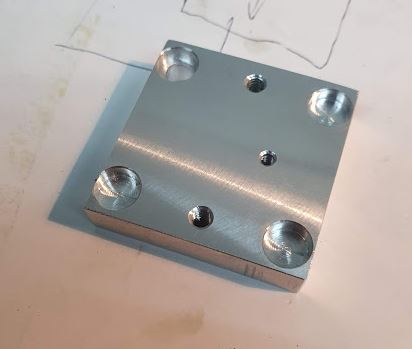
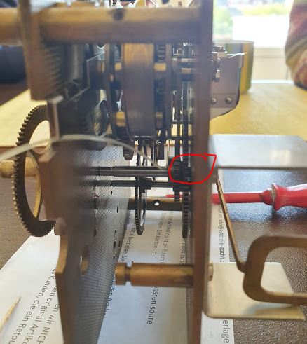
With the electric meter, the mechanical part is a bit more difficult, as there is no place to attach a screw or anything, so I decided to use a piece of plastic, precision made to fit the front cover recess, and a metal wire (spring bracket) to hold it in place.

At the right positions, openings have been milled so that the wheel can be “seen” by the IR detector (the wheel has a red mark, and 75 rounds per kWh consumed).

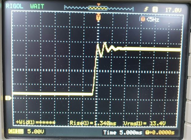
It needed some fine adjustment and tuning of the pick up threshold, and an algorithm to avoid false counting by introducing a dead-time after each pick-up event, because with the wheel turning fast, e.g., when 10 kW are drawn, there have been extra counts. This has now all been eliminated by proper adjustment, more margin of the IR detector.

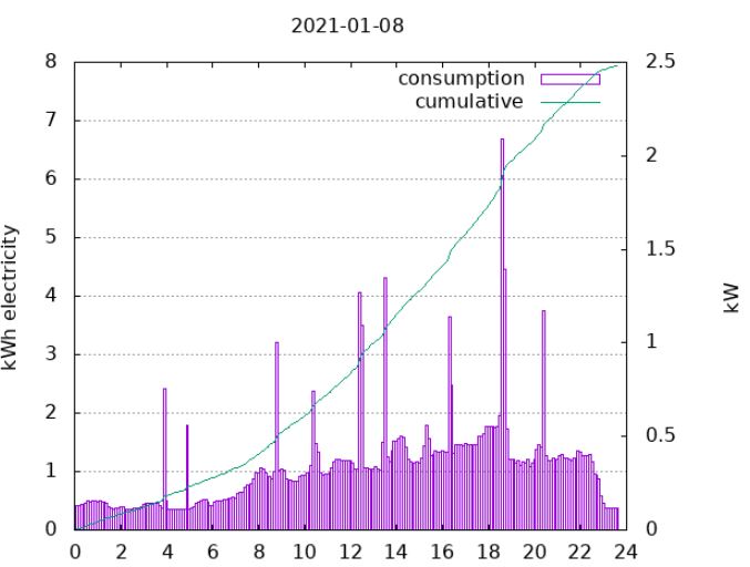
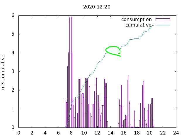
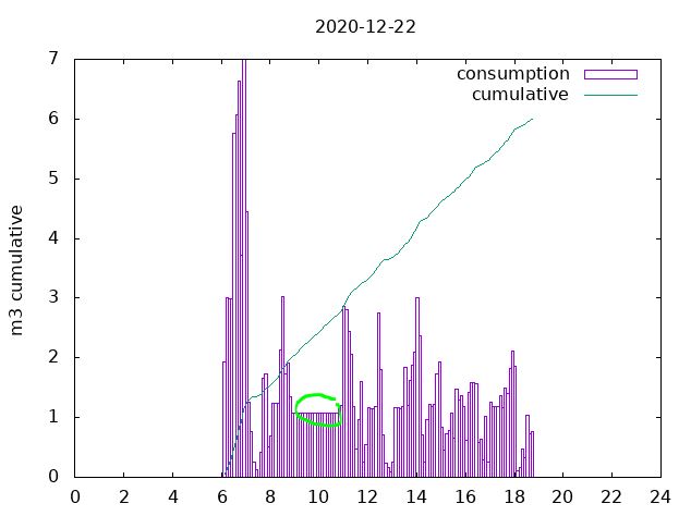
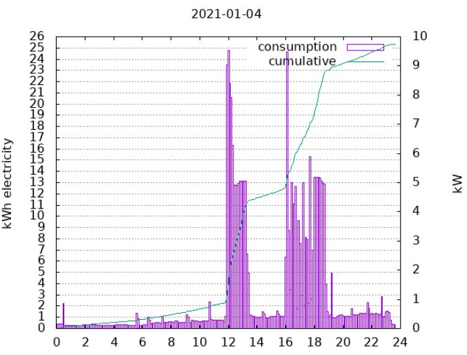
Some examples, with high power consumption in the workshop, i.e., 5 and 10 kW machinery and heaters in operation.

Additionally, the same system is used to record the living room floor temperature, in a corner, which is a pretty good representation of the heating system’s effect on the house. At nighttime, the heating is essentially stopped (13.5 degC as minimum temperature, which requires no heating unless it is a very cold night). The sensor is a DS18B20, which can be directly connected to the microcontroller with no further converters and delivers good accuracy.

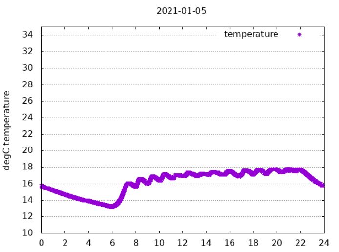
It is seen that the regulation has some on/off characteristics, but the temperature stability seem stable enough for the purpose.

If you want to do similar things or need the code, etc, just drop me a line.

Christmas Time: Honigkuchen (honey based cookies)

It is a long time favorite, and easily stores for some months – honey based cookies. Here is a good recipe.

500 g Honey
125 g Sugar
150 g Water (you may just add some more Honey if you don’t like to add refined sugar, but it makes the dough easier workable)
1 kg wheat flour (can be some coarser type wheat flour)
60-80 g Spice including anise, clove etc., a ready purchased mixture. Adjust quantity to strength of spice and your taste
25 g Ammoniumbicarbonate (“Hirschhornsalz”)
Pottash can also be added, by I didn’t add it, it will make the cookies flat.

First, mix and melt honey, water, sugar, at low heat. Add the other ingredients and work firmly. Let it rest for 2 or 3 days in the fridge (cover to avoid drying out).

Then, prepare cookies, and bake at about 200 degC for 8-10 minutes. These need to be well baked. Underside can be dark brown, but don’t burn them to bitterness.

The Honigkuchen can be stored in a well-closed container for 2 or 3 months no problem.

HP 4140B pA Meter/DC Voltage Source: some incorrect assumptions, but finally, a repair

Shortly prior to my departure from Japan I started repair of a HP 4140B. A very desirable instrument for semiconductor characterization. The issue remained that output “A” didn’t provide correct voltages, probably due to some issues in the amplifier.
Two month later, I have returned to Germany, and a spare LF256 J-FET opamp had arrived, so I thought it would be a quick fix – but to no avail.

Fitting the LF256 to the board – I usually leave some part of the old wire in the Teflon isolator, because I want to avoid soldering/melting the solder in the Teflon part – it is all difficult to clean up afterwards, so I prefer to solder the new part to some leftover wire, rather than contaminating the isolator.

But- with the new opamp installed, same symptom, no proper output, current limit function of channel A blinking, but the input of the opamp is good. So it must be something else down the chain. Another look at the schematic…

There is an analog switch, followed by a discrete linear amplifier with a dual J-FET input stage.
After some study of the analog switch (cutting a trace and checking it), the switch appears fine. Next in line, the dual J-FET, and in fact, this is dead – found it by measuring the E-B and C-B transition voltages with a diode tester (instrument powdered down and board removed!!), and the transistor around the FET shows largely different values compared to the working B channel. It is 1855-0049 HP part, available in some single piece quantities but expensive!

Looks still shiny and new, but it isn’t working.

Studying some NSN databases, found at least some data of this part, which had been manufactured in equivalent versions by some other manufacturers as well, probably in the 1970s.

It is a rather not so special depletion n-type J-FET. But it is a dual FET part, and while single J-FETs are no problem to get, dual FETs are rare specimens.

Even in their long past days, these didn’t come cheap… maybe something like 40 EUR a piece in today’s money.

So we need to do further study, and there are essentially two kinds of dual FETs – some that have a specially made dual die, with both FETs on one chip and coupled in various ways to keep them from drifting apart with temperature, etc., and the other kind, which is merely just two reasonably matched separate FETs in one case, for convenience more than anything (and for thermal match).

Screening through my inventory I found these 2N5457 FETs which have pretty similar electrical characteristics, in particular, zero-gate-voltage currents.

The parts I have are all quite uniform so there is no need to select a special pair.

With such replacement with similar parts, rather than identical parts, I think it is a good idea to take no risk, so I took the B-channel dual FET and transplanted it to the A channel. And the B channel, which is anyway only a secondary function of the instrument and doesn’t allow the same fast ramps and functions like the A-Channel, it will be definitely good enough to install the two FETs separately (closely together), rather than the original part.

The dual FET of the B channel replaced by two 2N5457.

The B channel dual FET 1855-0049 transplanted to the A channel.

With these repairs, the instrument powdered on just fine, and the output voltages were spot on without any need for alignment. Even the zero bias setting if the LF256, no need to adjust.

Induction range repair – just a couple of IGBTs, and a 20 Amp fuse

Recently, the induction cook-top of my SMEG range failed, leaving me with potentially expensive repair options quoted at above 1000 EUR, or to do some investigations myself. Surely, the latter option applies in my case. So, after receiving two spare IGBTs by mail, and a high current fuse that matches the “repair option” fuse holder of the cook-top, it took just a bit of soldering to get the thing up and running again.

Mounted the IGBTs, an easy job compared to the tedious mounting of all the coils and cables. It is not quite a service friendly design, and there are many sharp edges that can damage cables and your skin, so better wear gloves and handle everything with care.

After cooking on the range for a while, there is absolutely no problem at all, it’s a 20 dollar fix, if you don’t count your own time – maybe about two or three hours, mostly, to take out the electronics and put them back in.

A major move, and a defective CATV splitter

After returning from Japan to Germany early October, I decided to move to a new place, a larger property with ample workshop space and gardens.

Needless to say, a major effort with tons of heavy test equipment and other stuff piled up…

Apart from the heavy lifting, apart from tap water, electricity and a tight roof, a fast internet connection is the most essential thing. This took quite some more effort than expected. First, the grounding system of the house needed an upgrade (otherwise the internet cable company would refuse to install their amplifiers and cable modem), and, that done, there was not enough signal going in and out the house to allow for the 1 Gb/s connection…. first, they changed all the stuff inside of the house, a full upgrade, but to no avail, finally, they marked a spot on the sidewalk.

Only hours later, strong men showed up, digging up the ground in the search for the internet…

ads/2020/12/catv-digging.jpg”>

The connection here is delivered on CATV coaxial line for the last mile, so there is main line about 50 cm underneath the sidewalk, and there are taps/splitters, usually one splitter serving two houses.

From what I can tell, it is a 2x 15 dB tap, a quite common part in the CATV network. It took the crew just about half an hour to install. Great job.

The part, here is a clean shot, it has the connectors already mounted, and in the field, the cables are merely inserted and heatshrink tubing applied.

There are now a few interesting left-behinds, an old CATV house connection box with filters, I will test it out once there is more time.

After the installation job had been done one the road, it took just another two visits of the cable company to get all up and running! At least, they managed to do all this in less than a week.

SMEG CS19ID-6 Range: cold food only….

Recently, big disaster. My cooking range failed, not quite completely, but the right two of 5 induction hobs. It is not just a plain range, but a high end version large range, made in Italy…

It took a while to figure out how to disassemble it, and at a first glance, nothing visible, so I put it back together, and started to investigate the professional repair services…. quotations ranging from 900 EUR minimum, to 1500 EUR average cost to fix the error “E-5” that is now showing on the display.
Before going forward with the repair, I got some single hot plate so that at least cooking can continue, while dealing with a potentially lengthy repair.

A proper repair is done in a workshop, so I took out the whole hob assembly.

Upon close inspection, the filter assembly has a blown trace. It is a PCB trace acting as a fuse…

The copper of the trace deposited on the plastic cover nearby.

Fortunatly, the manufacturer, E.G.O. (a very famous German enterprise that makes most of the European induction range drivers) provided already a fuse holder to fit a US type 20 Amp slow-blow fuse.

Checking around, the left two IGBTs, IXGR40N60C2D1 are completely short.

That’s the full assembly, 74.470.061, with capacitors, a rectifier, and 2 IGBTs per hob.

For the time being, waiting for spare parts (ordered several more spares, and several fuses, just in case….). The IGBTs desoldered nicely, and I also checked the rectifier and all the diodes around, nothing suspicious.

Micro-Tel SG-811 Swept Signal Generator: another dead LH0021, and a design issue

After only a few hours of use since the last repair, the unit started to play up again. Simply, no output on all bands. A quick check revealed the issue, fortunately, no failure of the power supply, but again, the driver board for the oscillators, and again, the LH0021 power opamp isn’t delivering current.

By removing the wire that connect the LH0021 output to the YIG tuning coils, and feeding current from an external supply, all working great – fortunately. With no other stock at hand, I decided to move the power amp LH0021 from the (not normally used) filter driver board to the oscillator board, these boards are essentially the same design.

After that switch, it worked again – but only for another 30 minutes, then it failed again, another LH0021 burned out. How can it be??

No, I took all apart, including the mica washer, suspecting some short through the mica or similar issue (the heatsink is ground, but the case of the LH0021 is output). The mice is OK, but there is an issue with the screw hole and its plating. On the top side, is is plated as much as that it contacts the heatsink just slightly, probably, when it expands with heat, it causes the deadly short. Noteworthy – the driver board has the top side of the screw hole completely unplated!

Anyway, too many defective LH0021 yet, and this time I couldn’t find a cheap source. And not willing to pay USD 20 and take more chances for these parts to fail.

As luck would have it, there are some audio amps in my stock, quite common in lower-cost stereo amplifiers. About 20 W audio power, in an easy to use TO220 case, and despite being obsolete, these are ubiquitous, and low cost.

Normally, these are AC-coupled at input and output, and I didn’t find much reference to DC coupled uses. So I set up a little test circuit, and in fact, it provides a nice power opamp (unity gain stable).

Furthermore, the TDA2030 has both short-circuit and thermal overload protection. I wouldn’t call it indestructible, but chances are, that it would survive some adverse conditions.

Only trouble, there is no good space to mount the TO220 case to the heatsink. But a temporary setup will do for now.

With no other change of the circuits, all seems to work well, and also the frequency response seems OK. The LH0021 has about 15 kHz bandwidth, this can be easily met by the TDA2030A.

And in fact, it works well in the SG-811. All working and no need to align anything. Still, I would like to make sure the device has a proper heatsink. So, from a piece of scrap aluminum alloy plate, I machined a heat distribution plate, about 10 mm thick.

That’s the ready-machined parts, degreased with a bit of alcohol.

The distributor mounted well to the board, I cut threads into the metal block, so it is easy to affix to the board without any additional holes or modification.

To be not again trapped by some strange things, I also did some testing of the inrush current, power-on behavior and such (a current spike or reverse voltage may also damage the power amplifier). Also, mounted two more caps to the rails, and a dual-diode 48 V limiter.

However, the startup of the 18 V rail is good and clean.

Same fix applied to the filter board – there is enough space to fit the amplifier without any trouble.

Running at 18 GHz for a while, the temperature stabilized at about 60 degC, well in the range of good working conditions. A few hours later, the SG-811 is still working. So, with some luck, hopefully, a permanent repair.

ADF41020 PLL: mysterious failures, and a not so mysterious fix

For years I have been building PLL microwave frequency stabilizers using the marvelous Analog Devices ADF41020 circuit, however, while in all permanent installation there were never any issues, occasionally the inputs failed in my attenuator calibrator setup – essentially a set of two microwave receivers, a microwave source, and a ultra-precision directional coupler (Narda 5082) and a HP transfer switch.

A EIP counter is used to monitor the rough overall power level of the incident radiation, as well as to check the correctness of the frequency and providing the 10 MHz reference to the PLL system. Each PLL has a ADF41020 board as the key input element.

One day, I noticed some ground loop currents, and again, one of the boards failed. So I decided to dig into it and solve it once and for all. Strangely, the board of the generator had never failed.
Looking at the datasheet, there are input diodes that may be easily destroyed by DC current flowing into the ADF41020 RF input.

It can’t tolerate voltages below ground or above 3 V much, so it is quite clear that some ground loops or other potential shifts can destroy it.

Further investigation showed that the RF sample output of the Micro-Tel SG 811 generator actually is AC-coupled (there must be some decoupling within the directional coupler that is getting the signal out, or in the switch leading to the sample output – which is quite possible because there are PIN diode switches inside that normally need DC blocking caps to work). The Micro-Tel 1295 receiver however have the center pin of the RF sample output connected to ground via a 50 Ohms resistor at the other side of the directional coupler taking some power off the line. So it is at least clear that the DC current from the center pin caused the ADF41020 to fail. Easily solved, added some 2.2 pF microwave caps. These are tiny parts, 0402 size, and remarkably cheap for their performance.

Soldering needs a steady hand, and definitely you don’t want to put a lost of stress on the board, which is mounted by the SMA connector only. Probably it could be made more rigid with epoxy, but I rather like to treat such PLL equipment and microwave gear with great care, because these are solid structures, but don’t handle impact and bending well.

After put all back together, so far no failures at all.

Siemens Electric Master Clock: after some years, a little repair

My trusty Siemens master clock, after some years of service without any trouble, it needed repair. The electromagnet coil that charges the weight, it is triggered by contacts that got dirty over time. So I cleaned all well with contact cleaner and some ultrafine abrasive paper.

With these little repairs complete, the clock showed another issue. It just stopped after some random time, and that is no good for a Master Clock. Generally speaking, pendulum clocks that stop oscillation randomly are difficult to fix. It may be dirt in some gears or bearings, it may be incorrect adjustment of the escape wheel, it may be some local disturbance.
Fortunately, the full clockworks can be removed without touching the Invar pendulum.

There are connectors at the top, well large in size, and with some silk spun wire.

Upon closer inspection, one of the main gears, which also drives the minute hand, showed issues. It is not fixed in position, but moved in and out. How can it be? When it gets out too far, there won’t be any reliable force transmitted to the pendulum, so it will eventually stop.

There is a washer, brass, on the back side of the movement, and this is supposed to hold the axle in a fixed position, while allowing it to spin freely.

Somehow, this washer had worn out. So I just rotated it.

Giving the clockworks a good clean and oil (only special clock oil made for medium-heavy clocks supposed to be used!), but without a full disassembly.

Now it is ticking away again, and showing the time, day and night.

SimonsDialogs – A wild collection of random thoughts, observations and learnings. Presented by Simon.