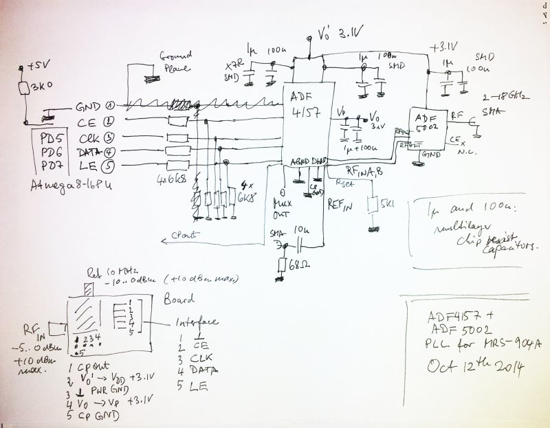
Some final parts added to the MSR-904A digital interface/PLL: the actual PLL circuit (frontend), an Analog Devices ADF4157 fractional-N PLL, together with an ADF5002 8:1 prescaler. The phase detector is set at 1.25 MHz, to allow 10 MHz integer-only steps. Some experimentation with other phase detector frequencies might follow later.
Here – the schematic of the PLL frontend. The circit is wired point-to-point, sure enough, with VERY short wires, soldered using a microscoped – hope you have a steady hand. After a quick test (using the MUX output of the ADF4157), the wires and the very tiny ADF gadgets, all sealed with a few drops of epoxy.
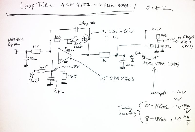
On the main board, the PLL loop filter. Build around the remaining half of the already installed OPA2703 (other half used for the DAC output buffer).
With all these parts now put together, to do some basic tests on the PLL – a Gigatronics 605 Microwave Synthesizer was connected to the MSR-904A input, and the LO sample output of the MSR-904A connected to PLL. A sample of the “LO sample” taken by a broadband -10 dB coupler is used to monitor the frequency, using an EIP 545A. The 10 MHz reference output of the EIP is used as the ADF4157 reference.
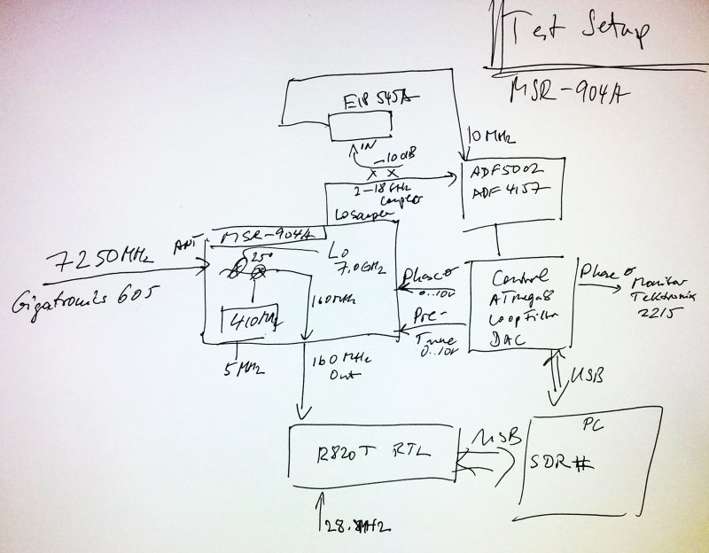
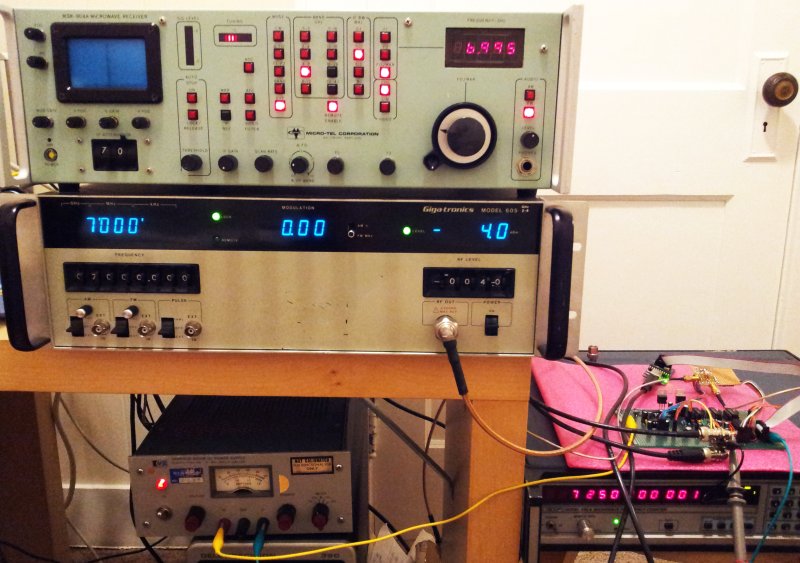
The MSR-904A down-converts the signal to a first 250 MHz IF (by fundamental LO), the 250 MHz IF is then mixed with 410 MHz (this can be locked to a 5 MHz signal – not locked at the moment, but the signal is very clean and stable anyway).
The 160 MHz 2nd IF is available at the rear panel, and connected to a R820T RTL SDR. This is a very handy method to monitor noise, and do some basic adjustments on the PLL. Using headphones – and the human ear as a phase noise meter… more quantitative analysis to follow.
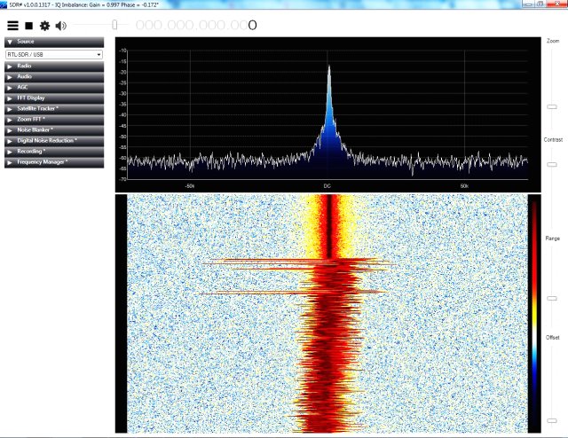
Here, the transition from manually controlled CW mode, to PLL controlled mode.
A close-up:
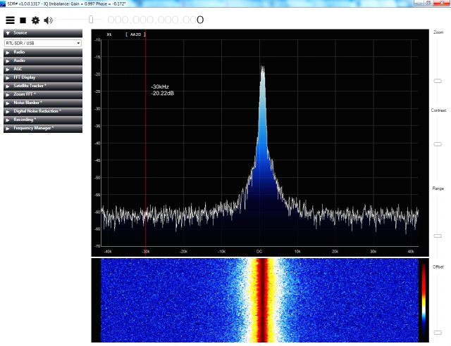
For these tests, the LO was locked at 7.25 GHz, receiving a signal at 7.0 GHz (SDR offset set to about 160 MHz).
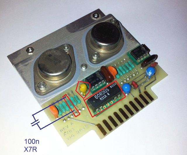
Note – same as for the Micro-Tel 1295, and the SG-811 – the YIG driver has a bandwidth limit (by a 100 uF Tantalum capacitor – and a 499 k resistor!) that is controlled by a reed relais on the YIG driver. This doesn’t allow low phase noise operation, even with the best PLL. Well, 100 uF is a bit too much. Therefore, a 100 n capacitor was added – this is enough to suppress most of the noise of the YIG driver stage, and still the circuit remains fast enough for full band sweeps at moderate scan rates. Might modify this later, by adding a bit of logic that adds the 100 n capacitor only when the external frequency control is active, but disconnects it during full band sweep, etc.