Metalworking: strange defects of long-used tools

Recently, I found two strange defects in my workshop, noteworthy to write it down.

Ever since I expanded my workshop I notices some losses of compressed air, i.e., when coming back after a business trip, the pressure of the compressed air pipework is down from normally 6.5 bars, to only 2-3 bars, or even less after a longer vacation. I had attributed it to some leaking air gun or something like that, but finally I did a search and found various leaks at one distribution point.

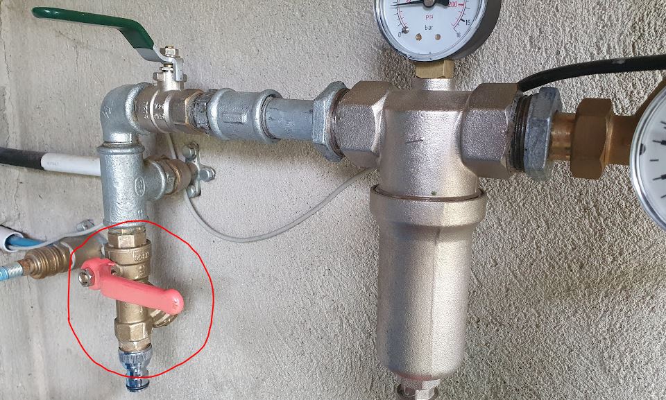
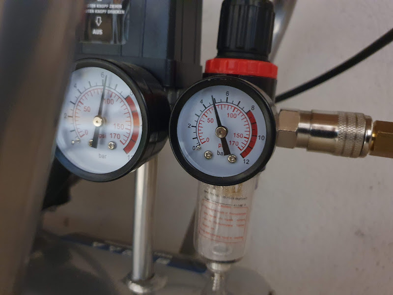
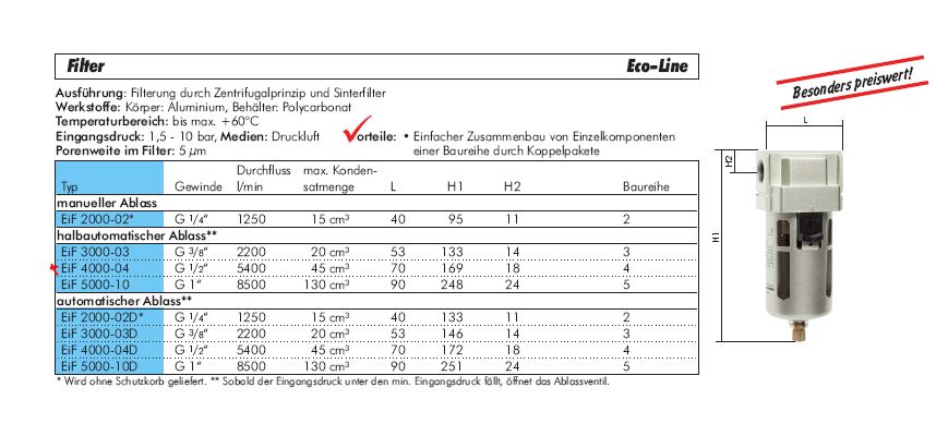
(1) the water mist filter had a leak at the drain valve — fixed it by closing it altogether. There is not too much water collected, it is installed only to avoid dust and such getting into the system further downstream.
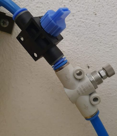
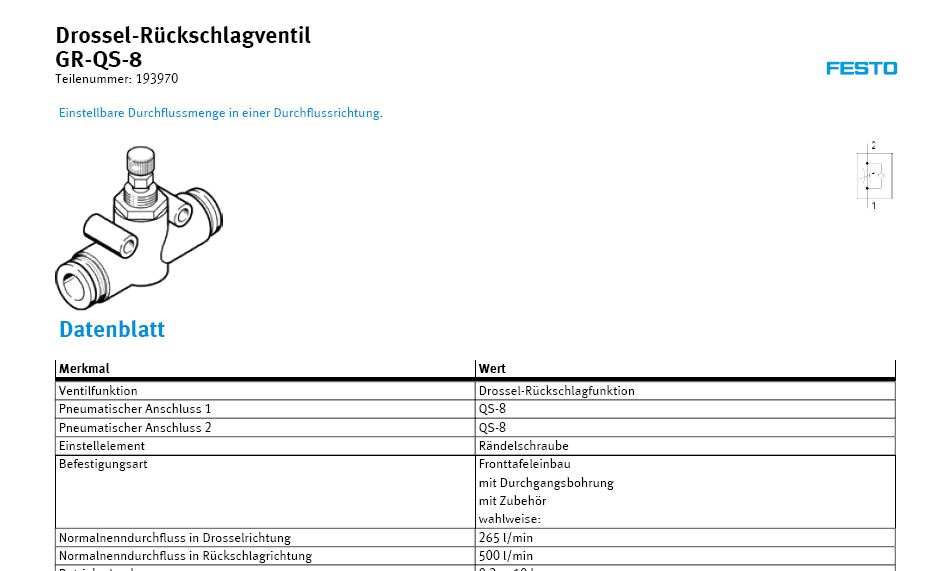
(2) one of the fitting was leaking, because strangely there are some air fittings available that neither have a seal surface, nor conical thread, to it is hard to get it tight by tread tape in the first place (sometime I resorted to gluing-in those fittings with Epoxy glue).
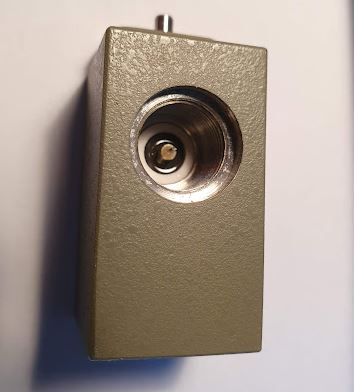
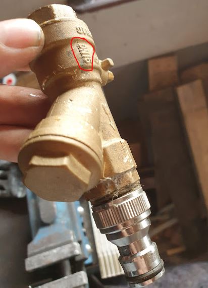
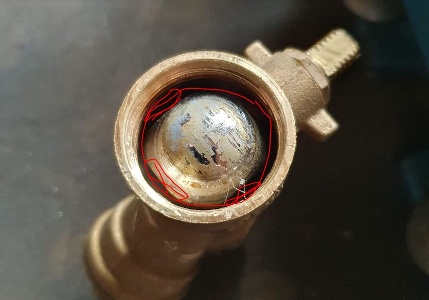
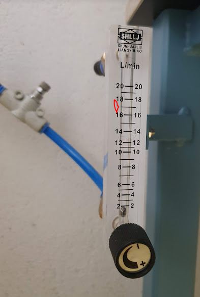
(3) Still, when checking with some soapy water – bubbles at the distribution fitting (5 connections 1/2″). Strange, strange, strange.

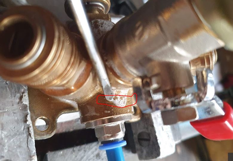
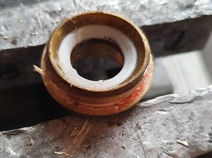
Clearly, a defective casting with a hairline crack leak. Maybe the temperatures or the mold or the liquid brass were not right, or the pouring wasn’t steady enough.

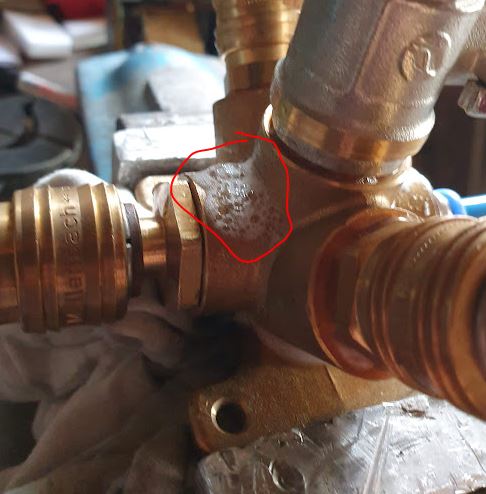
The defect line goes all around the fitting, otherwise I would have tried to file it out and solder it tight. Anyway, it is not worthwhile to fix such part at the risk of it failing again. So I replaced it with a new fitting at the cost of EUR 9.90 and at least 3 hours of work to get it all investigated, replaced, fitted and leak tested. Maybe a good idea to fully upgrade the pressurized air system of my workshop, which is now a combination of various distribution pieces, hoses, connectors. But there are trade-offs of perfection, cost, and efficiency — I have actually installed some air pressure distribution pipes for others (like, polyamide pipe, PE-Al composite pipe), but at my own workshop, I will be dealing with a less perfect system, at least, the major leaks have now been found and eliminated.

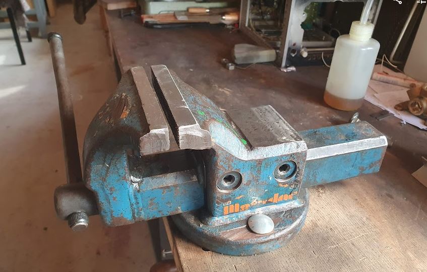
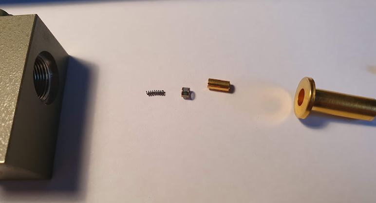
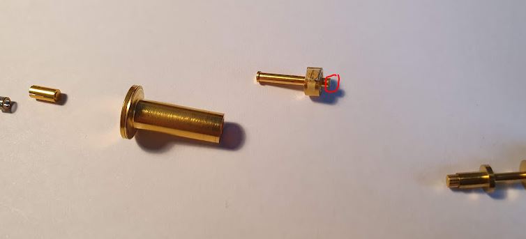
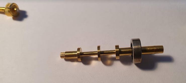
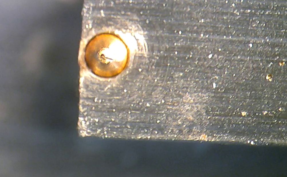
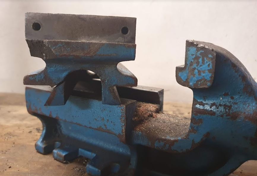
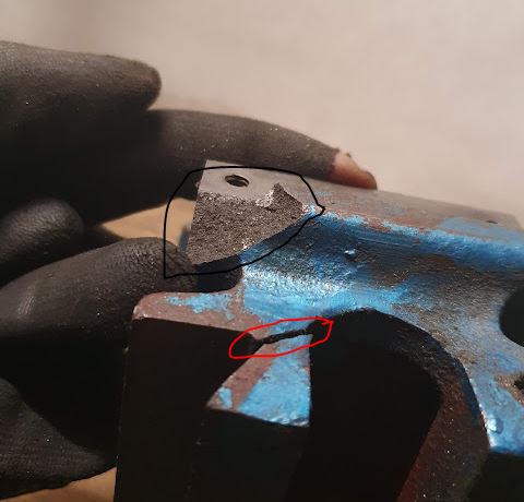
Another instance of strange failures, I noticed some problems with a bench vice, the smaller size vice I use regularly, and have been using since my childhood. If I remember right, I bought it for something like 35 Deutschmarks way back around ~1990. After all these years, it had some failures, the spindle pin sheared off once (maybe because I tightened it too much), and also a retaining piece of the front part of the spindle wore out (probably very soft steel and insufficient lubrication). Also some part of the casting broke off before, circled in black. Now, I almost injured myself as a part came loose unexpectedly, finally, as they say, always check the tool before you use it.

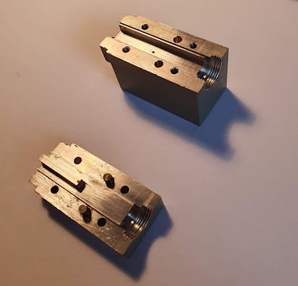
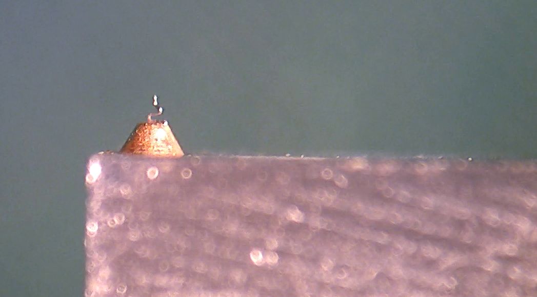
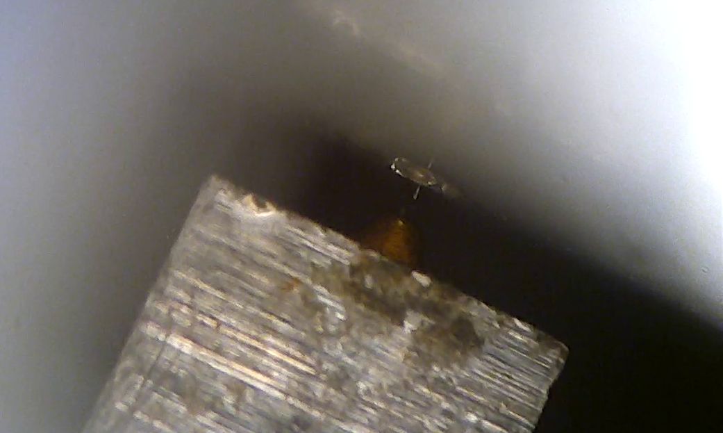
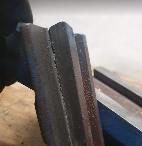
Didn’t need to go far, a major crack of the dovetail guideway.

It is cracked through, but holding on enough so that the defect is not easily seen without disassembly.

Finally, a cast iron bench vice, after 33 years of service (not always careful use), it may eventually break.

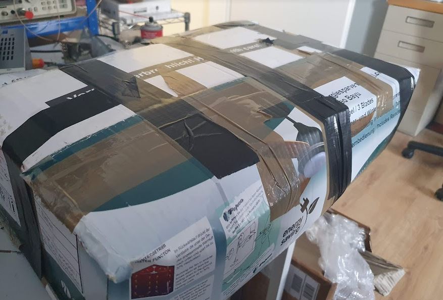
For replacement, I wanted a slightly bigger bench vice, 115 mm width. Also, a solid steel vice that is not too bulky and has a strong grip. These don’t come cheap, but I found a good (but rusty) Peddinghaus Matador steel vice for 35 EUR used, listed in online adds.

After some cleaning, adjustment, and other TLC, it is installed on the bench and working great. Definitely a step up.

Meridian 506 CD Player: after 5 years, in need for more attention

Recently, I had two instances of equipment coming back after some year – with different defects that at their first visit in my workshop. One device is the Meridian 506, a high-class CD player that is popular with hifi enthusiasts, and has been marketed for many years in various different versions. Earlier I had fixed some design issues with the motor driver of the CD deck, see Meridian 506 CD Player: a hot driver.

This time, it wouldn’t detect any CDs, and made some noises. The deck was still opening fine. After looking around, there is no obvious defect, the power supplies are good. All the service modes work – just that I can’t get it read discs or even lock on tracks, it just spins up, then stops.

Reading through all various posts, it seems clearly related to the CD head assembly, this version of the 506 uses a CDM 4/19 Philips laser head assembly, and these are known to wear out over time, i.e., the laser will show aging, and then the mechanism can’t lock on the CD.

Well, easy enough, I found a CD 480 player cheaply as used goods, and this has the desired CDM 4/19.

It arrived strangely packed, but well, better strangely packed than insufficiently packed. Indeed, a lot of styrofoam, chips and paper inside.

Inside, a very simple assembly, much lighter than the Meridian deck. Just some thin plastic.

Easily disassembled the donor.

There are some changes necessary – the hub is different, but can be removed with simple tools (plastic tools) and switched.

Well, all this done, unfortunately —– no success. Still same symptoms. Next, poking around the main TDA chip, there are no signals that are of any use. Strange. Normally it should at least start reading and locking, but it doesn’t (not that the CD drive uses a feedback loop to keep the head on the track, by adjusting the laser arm coil current according the the laser feedback; in these drives, the laser arm is driven by a coil).

After some further study, finally realized that the CD is spinning the wrong way. How can that be? Seems like a defective motor driver! On the small board of the CD deck, there are two L272, and one of them is terribly hot. Not good.

The L272 has long been obsolete, but I would two pieces cheaply on a Chinese website, these were apparently no new but recovered from used equipment. Well, no problem, I rather buy used parts than fake parts.

With these repairs done (not easy because the soldering of the L272 is very strong, need to put a lot of heat to the small board because all the ground pins are firmly connected to a ground plane), the Meridian is working great again, let it play for several hours with no skipping.

And, we now still have a spare laser head assembly should it fail next.

Another Micro-Tel 1295 Precision Attenuation Measurement Receiver: irresistible green

I am trying hard to resist the temptation of buying more test equipment, but the Micro-tel special green color has a hypnotic effect on me, and combined with the right price, I could not resist to buy one more Micro-tel 1295 receiver. These are very capable 0.01~40 GHz fundamental-mixing receiver (fundamental mixer until 18 GHz, above that, harmonic mixer), with very large range, like, 120 dB, and 0.001 dB attenuation resolution. Ideally suited to calibrate attenuators or to check antennas, etc.

The unit – offered as non-working – arrived very well packed. Unfortunately, many people send sensitive equipment in some thin cardboard boxes. This particular equipment cost close to 85 kEUR in 1989, plus mixers. Also, it has long been under export control from the US, because of its unique range and accuracy.

Bubble wrap, other fibre wrap inside.

Finally all in foil.

The defect, it doesn’t show any reading on the display, and both the HI and LO leds are on, which is abnormal. The 1295 has a 12 dB range bolometer detector, any signal below 0.5 dB or above 12.5 dB will light up the LO or HI lamp, and you would need to select another 10 dB step of the IF attenuator (a high precision 30 MHz attenuator), or let the automatic attenuation selector do the job.

There are many boards inside, but all nicely numbered and with instructions in the manual.

The HI and LO level detection is done on the A3B2 assy.

According the the schematic, U2, a MC1458 generic dual opamp is switching the LEDs and providing signals to drive the automatic attenuation selector.

A quick check revealed that U2 is defective, so I replaced it quickly, and this already solved the issue and brought back the display.

Another trouble related to unstable lock of the 2.3 GHZ auxiliary LO that is used for the 0.01-2 GHz range (which uses a two-stage down mixing).

Fortunately, I had a spare 2.3 GHz from my parts unit (which I bought years ago – a partial unit – while I was living in the US). That part was missing one of its covers, and had also some issues earlier, but I had fixed it a while back just for curiosity. Now I can fix the unstable 2.3 GHz removed from the unit during next winter. It has a 2.3 GHz VCO, a 100 MHz local oscillator and a PLL inside.

After calibrating all the oscillator frequencies, which went without trouble, I noticed that the top 120 dB attenuator was 0.04 dB off, well, not a big deviation, but I would rather have the unit working perfectly. So I removed the attenuator for further study.

It is build with really high quality relais, more than USD 50 (each!!), and some precision resistors.

Nothing could be found wrong with the unit by visual inspection.

Also I used the VNA to check the attenuator, and all seems well working.

All the 3 segments, virtually equal at 10 dB each.

Finally, I put everything back together, a little clueless, but, now, for some reason, all is working and stable. Maybe it was some lose connector, or other strange effect that is now gone. All attenuators calibrated perfectly, using by HP 3335A level generator (which has a top-accuracy attenuator).

Finally the 1295, working just perfectly fine. Maybe better than ever before.

Interestingly, as with all of these Micro-tel devices, the side and top/bottom panels were painted with various kinds of special military paint – some with a rubberized paint that will dissolve into some gluey substance over time, some with a type of “abrasive” paint, other already re-painted in forest green.

The paint has very large and hard grit, almost like sandpaper. But I will leave it untouched, it seems the original looks for this serial number range (the 1295 seems to have been in production for 10+ years).

Now, a little gallery of all my Micro-tel 1295 receivers: the first two, part of my frequency-locked attenuator calibrator (can measure reflection and transmission at the same time).

One as part of an E-band (60-90 GHz down-converter).

Any now, already two spare units in perfect calibration.

Still, in the basement, a box of spares… likely I won’t run short of receivers soon. Maybe even buy another one should it come around.

Watkins-Johnson SE222-50 Backward Wave Oscillator: the magic helix

Recently, I got a Marconi Instruments Model 6651 RF Plug-in (26.5-40 GHz), for the 6600 sweep generator. These were basically the 1st generation sweep generators extending into the millimeter wave region.

A number of plug-ins were available, mostly based on Watkins-Johnson BWO (backward wave oscillators), which are a particular type of electron tube.

These sweepers were first introduced in the late 1960s, early 1970s. New plug-ins became available as development of BWOs and similar sources advanced.

I have no price list, but surely these items came at a hefty price tag in these early days, even not quite cheap today.

My unit had a pretty “new” 1990 date-code BWO, I expect, it had been replaced by its former university owner at least once, also the cables and connectors of the BWO looks newer compared to the rest of the plug-in. Because of their nature, the BWOs only have a limited life-time, a few 1000 hours at best.

There are numerous warning labels, because to focus the electron beam, a strong magnetic field is needed.

The output is a gold-plated waveguide flange, for Ku-band waveguides.

The general layout of a BWO: there is an electron gun, producing, in our case, a hollow electron beam, with the necessary heater, kathode, anode. Then, the helix, and the collector (which is basically at helix potential or a little bit higher, say, 100 volts higher. The helix voltage is quite high, for exmaple, 1~1.5 kV.

While there is no information from Watkins-Johnson available online for any of these devices, a lot can be learned from related Hewlett-Packard microwave sweeper plug-ins (8697A), where (arguable) the same or very similar BWO has been used (some HP units may use Varian BWOs).

Unfortunately, after quite some effort with high voltages and pretty dangerous tests, it became clear that the tube barely gave some power. Maybe, because it had not been operated for a long time (some people and datasheets say that the BWO should be run at last once every 6 months, or similar, to preserve its function…).

But anyway, I have other, more stable and easy to use sources for this range, so I didn’t want to scrap the BWO without having a closer look at this. When do you normally get a chance to check out the secret workings of such marvelous devices!

First things first, hidden inside a heavy magnet, silicon rubber, and a waveguide coupler: the tube. A very mysterious piece of engineering, only a few companies ever mastered to produce these.

Also by the numbers and hand-writing, pretty clear that these units were all hand-made and assembled by engineers and highly skilled people.

The mount is all gold plated, a tapered wave guide eventually bent by 90°, so the microwave radian can be coupled from a small gap in the silver coating of the tube, to the outlet. This tube was meant to generate about 10 dBm.

The helix at the collector end.

You can see, the helix is kept centered by 3 glass (quarz?) rods, these rods are just held in place by the tension of the helix, but normally won’t move during operation and shipment. Surely, will all the glass-metal interfaces, mounts and connection points, it is no good idea to drop these units – some interfaces may break, or mis-align beyond repair. Furthermore, several Watts of powder will need to be dissipated, calling for a reasonably elaborate design of the mount not only to conduct the microwave radiation from the tube to the output, but also to dissipate the heat from the collector and helix.

All the high voltage socket part is embedded in two layers of silicon rubber. First they put some denser rubber around the socket to fix everything in place, probably run some tests, and then sealed it all by filling the further space with some pretty soft, highly filled silicon rubber. What they didn’t consider – the cable also has silicon isolation, and deteriorates in contact with other silicon materials. This may be one of the reasons for the unstable operation, because some wires were pretty close and the isolation seems very brittle.

Furthermore, I did some measurements of the critical parts, just in case I would even want to fabricate own BWOs, at least I have some working dimensions to start with.

The helix is normally made from flat molybdenum strip. At the bottom (gun end) it is mounted to a small ring. Scale is 210 px per 1 mm, in case you want to take dimensions…

A typical power supply – I am thinking about building a BWO power supply for some other old BWOs I have around (for other frequency regions), but it is fairly involved – the old design used high voltage 2 kV transformer with further high-voltage stable windings to provide the collector offset voltage, several expensive high voltage capacitors, and high voltage regulation vacuum tubes. I think it will be a good challenge for winter to build a 2 kV regulated and low-ripple power supply, solid state, probably with some series-connected MOSFETs.

Any of such future supplies will need a pretty special plug: heater voltage, anode and cathode voltages, helix voltage, collector voltage. At least I can go without any analog linearization voltage, if I manage to make the helix supply digitally controllable.

Inside the 6651 plug-in the BWO is connected to the board with some screw terminals. Seems to work well even at the high voltages. Surely there is no touch protection for these devices, just a few warnings not to get too close!

Wood and Steel, covered in Paint: a new garden bench

Recently, some heavy metal work in the precision workshop. Amongst other projects, I decide to build a new bench, to set it up behind the workshop building, to enjoy warm evenings during summer. Surely you could buy a bench, but I wanted certain dimensions, in particular, flat and somewhat wider seat area. A rough sketch shows the main dimensions. A cushion can be added, it matches 200 cm wide, 50 cm deep size.

All is made from solid flat hot rolled steel, one piece bent (after heating it with an oxygen torch, and using a small bending fixture), the other pieces welded (TIG).

All the angles were nicely hit.

I made a full size template drawn on stiff cardboard, so the welding and alignment could be easily done, then, fine adjustment by using the electronic level.

To get the right angles I had a look at some benches in public parks, etc., better to compare new design and existing know-how!

The seat, a little inclination to make sure water will drain.

The wood, douglas fir, it has a fair amount of resin and is quite resistant against weathering. It may darken, but it is not prone to rotting. I painted it with some sun-protecting varnish, two layers.
My uncle kindly provided the wood, from my ancestors village, ready to use. Saved a lot of time, compared to cutting and preparing the wood with my humble small woodworking tools.

The metal parts, carefully removed the rolling scale, added rust-proofing primer, and then two layers of solvent based lacquer. You could also consider hot zinc treatment, but such solid steel, painted, should last a hundred years, or longer.

Finally, after some hours of work, and drying the varnish for 1 week during a business trip: finished and at its final place. Very comfortable!

HP 11517A aka 08747-60022 Harmonic Mixer: a little study of a very intriguing device

As part of a HP R8747A 26.5-40 GHz reflection/transmission test unit (for the 8411A network analyzer; 6300 USD in 1973 — about 40 kEUR today), I got two HP 08747-60022 harmonic mixers, one didn’t seem to work right, the diode has just 0.2 V voltage drop. These were fairly fragile devices, only designed for 1 mW of power, and very static sensitive, point contact devices.
In addition to the regular 11517A, the 08747-60022 has a bias connection (needs about 1.5 V DC bias, center positive).

The main unit can work from 12 to about 40 GHz, with a set of adaptor waveguides.

The unit can be taken apart, all precision machined.

The diode is pressed in, on some holder (haven’t tried to remove it from the case).

There are several other precision parts, a coaxial resistor, held on to the diode with a spring.

There is also a spacer, with a very flat capacitor, a DC block. The spacer is modified to connect the center conductor to a surface at the perimeter (used for DC bias).

Further up, there is a low-pass, machined from a single piece and gold plated.

The N-type connector, stainless, is screwed on.

The DC bias uses a small 1.5 kOhms resistor, and a custom connector, so that the resistor is pushed onto the spacers’s connection.

Here, a quick schematic. Seems a lot of engineering went into this device…

Finally, we need a microscope to study further here, the diode (the square), about 0.25 mm side length. It is isolated from the case by an air gap.

The diode is made by a contact junction, a small tungsten(?) whisker.

Probably, this whisker needed some adjustment during manufacturing. I tried to adjust it a bit, but this didn’t change the diode characteristics of my broken unit, unfortunately (anyway, these devices are more for study than for use; currently using only cartridge-based diode mixers).

Also, looking into the waveguide of the assembled mixer, with good long-range optics, I could get a shot of the actual point contact in action. Very interesting historic technology.

Spring repairs: Fixing and frost-proofing ball valve

Recently, I have been setting up the watering system for my vegetable garden again. In my area, the soil is a little sandy, not bad for growing vegetables because slugs and snails don’t like such soil, but surely it needs proper watering.
All in all it is about 200 meters of 16 mm drip irrigation pipe, 16 mm size, with drippers every ~33 cm, nominal 2.1 L/h each. The system is run at about 1.5 bar. Some specific plants like pumpkins and certain berry shrubs in other area of the garden have their own supply by 4 mm tubing and individual adjustable drippers.

In the past years, the system has severed me well, and just last year, I have upgraded the water supply by setting up a new well. So there is plenty of water, and every day, at least in summer, the system supplies about 400 L a day, in two portions (like, at 6:30 am and 6:30 pm). Glad I don’t have to carry all that water.

All the water system, pump and distribution piping had been empty over winter, to avoid frost damage to the pipes. I keep the ball valves at about 45° angle, but this year this didn’t help to prevent damage to one of the valves (all the other valves are OK).

It is a combined, low cost China-made ball valve with strainer, I bought two of these some years back.

It is tight when closed, but when opened, water comes out at the crack indicated in the picture.

How can this have frost damage? Well, with the pipe empty, it should be safe? There is considerable dead space in this valve, the ball also has an indentation (cut-out) at the side opposite to the handle. It is brass, chromium plated.

As luck would have it, I had the second valve still in a box, it had been in service for some years until someone broke-off the handle (never throw away parts that may be suitable as spare part donor…). Surely it would be quick to just replace it, potentially, even with a better quality ball valve, etc., but why now study it and fix it?

Breaking open the valve, the two parts are screwed together fairly hard, and glued with some kind of epoxy or similar glue.

But nothing that can withstand a large spanner and a pipe wrench! So, the front part with the PTFE seal looks good. Also the spare valve (with the handle missing/broken off) was disassembled in no time.

Now, how to frost-proof ball valves? It is quite easy, and a well-known trick. Just dill a hole, about 3-4 mm in the far side (low pressure side) of the ball, then it will drain the dead space, when left open (or at an angle).

It is essential to remove any burrs, so I countersunk the hole, and polished the edge with some find sandpaper.

Everything put back together, I used some acrylic compound to seal and tighten the screw threads of the two-part valve. Good as new!

Fixing a really-high-frequency phase locked oscillator: a noisy opamp and a little bit of sticky tape

Recently I got hold of a really marvelous bit of kit, an assembly of millimeter wave phase locked oscillator, all the way from 60 to 89 GHz. It is already 35 years old, but all based on solid state Gunn/Impatt oscillators, so there is little aging. For each frequency (there are 5 discrete frequencies), there is a full assembly of reference upconverter (100 MHz reference to some intermediate frequency in the 6-12 GHz range), a voltage controlled fundamental oscillator (e.g., bias-tuned Gunn diode), the necessary isolators and splitters and occasional attenuator, along with a harmonic mixer. The IF is 100 MHz or 200 MHz, depending on the unit.
Only one of the oscillators has been more than 20 kEUR in 1988 currency, and there are five such assemblies on this plate, along with control equipment and power supply…

Only one of the sources is playing up, not achieving phase lock, it is the 79 GHz oscillator. Notably, some of the small screws are missing and the lid of the oscillator cavity has been removed, which points to prior repair attempts. The Gunn has a protection network, a 2.2 µF capacitor in parallel with a ~10 Ohms, ~470n series network — this is to protect the Gunn diode from the inductance of the bias current supply (when the diode snaps-off according to its characteristics, it will induce a very fast current spike that could increase the voltage at the diode above its damage threshold).

Upon close inspection, the 2.2 µF capacitor had been tampered with, bad soldering, only one end connected, and in reverse polarity (it is a high-reliability tantalum cap).

When checking the down-coverted output, there is no stability at all, it has a very strange FM modulation. What could be the root cause?

Checked a few items:
(1) Upconverted reference, 11.3 GHz (7th harmonic will be 79.1 GHz): it is a very clean and stable signal, well locked without any visible noise.
(2) Checked all the cables and connectors by pushing gently, no sign of any trouble, all unchanged.
(3) The supply voltages are all practically noise free.
(4) Also fixed the 2.2 µF capacitor at the gunn diode cavity. No particular effect.

(5) Disconnected all the phase lock, bias driver, and driving the oscillator from an external supply.

Finally, with just an ordinary power supply connected and the voltage ramping up (don’t ramp it up too slowly or let the oscillator sit in an unstable region or at the Gunn peak current for any length of time!), there is a stable (surely, non phase-locked) output, but none of the strange modulation. So it seems, the oscillator is good. But wait, with some wobbling and touching on the part, it is shorting out the supply. Hmm. Time to go a little deeper, and I decided to remove the biasing rod.

Just for explanation, the biasing rod is isolated from the cavity (the metal block holding the diode, with the waveguide cavity in the middle), and conducts the current to the diode, which is at the tip of a metal screw holder.

Under the microscope, the very thin isolating tape (looks like some PET/Mylar transformer tape) is quite damaged and some metal of the bias rod exposed. Also the spring holding down the rod on the diode (which is fixed by a nylon screw) can contact the case easily. So all was newly isolated, and the screw and spring positioned carefully. Surely with all the soldering at the capacitor, things may have shifted a little. At least now no isolation problems any more. Sometimes when switching the oscillators on the assembly, the 79 GHz signal is not coming up, the Gunn drawing much less current. But it can be fixed by just power cycling the assembly, so it seems to be some rise time issue of the power supply.

This is the driver circuit, it has a hybrid high-speed Kennedy electronics 722 amplifier, but the low frequency path is a common NE5532 low noise opamp.

After checking around the low frequency path, the opamp seems to introduce some noise, note that for this level of noise at GHz levels, a few millivolts are more than enough to cause a lot of disturbance.
Fortunately, the opamp was socketed, so I replaced it with a OPA2277, which has about the same noise compared to the (low-noise) NE5532, and much lower offset voltage drift, and 40 dB better CMRR, excellent low frequency characteristics, and lower gain at >1 MHz.

Now, with stable current drive, we can measure the output power (downconverted by an harmonic mixer driven by a 11.45 GHz source, 7th harmonic: 80.15 GHz — shown is the minus mixing product, i.e., 79.0 GHz correspond to 80.15-79=1.15 GHz).

You can see clearly, the oscillator has good power from 79.1~79.25 GHz, but falling down just around 79.0 GHz. Note that at such high frequency, every mW counts…

After some thinking, I decided to try to lock at 79.2 GHz, and as it turns out, it is working fine at that frequency. With the 11.3×6=79.1 GHz, and 100 MHz IF, it works out, and the PLL doesn’t seem to be affected, regardless if you use the minus or plus side IF.

The IF signal can be probed conveniently at a test port, it is pretty clean.

Also the down-converted signals look good (this is 10 MHz span at 79.2 GHz center, corresponding to 80.15-79.2=0.95 GHz downconverted).

Also the close-in side bands are good and a very clean signal.

Outdoor movie theater: a digital projector ceiling mount

In preparation for warm spring weather and long summer nights I am already gearing up my outdoors installations, in particular, a video projector will be handy to screen some movies.
It will be working together with a Miracast Wifi display, so it can show streams from practically any device.

The projector is a fairly lightweight model, because I only desire an about 150 cm wide screen.

There are various commercial ceiling mounts, but they all seem about flimsy and inaccurate to adjust. So I quickly fabricated a precision-adjustable mount.

First, a metal plate was affixed the the projector, with a standard UNC 1/4″-20 screw. It is about 10 mm thick hard aluminum, just a piece of leftover scrap (that’s why there are various holes in it).

On the projector side, a 1 mm NBR rubber plate is used to avoid movement and scratches.

The adjustment uses three M6 screws, 1 mm pitch will allow very precision adjustment by Allen key.

For the ceiling side, we use an 18 mm thick piece of plywood, and a M10 bolt. Surely, a longer bolt, rod or pipe could be used depending on the needed distance and rigidity. For the current setup, the M10 bolt is plenty rigid enough.

There are three springs (stainless) to keep the holding plate – mounting plate system tensioned so that the adjustment screws can work precisely.

Still, we need to get a suitable projection screen, and some speaker.

But already now looking forward to various summer movie screenings.

Laser cutter setup: air supply, off-gas and various cutting tests

Finally I find some time to document all the remaining parts of the laser cutter, Workshop Upgrade: Laser cutter and engraver SCULPFUN S9. The cutter itself is just the common off-the-shelf kit, but the air nozzle and enclosure has been custom made. If you want to cut wood, paper, plastics, there will be a lot of bad-smelling and potentially toxic fumes, so better you enclose the machine and provide adequate ventilation. Also, for wood, paper and such, you will need a strong air flow to ensure clean cutting without burn marks.

The setup is now arranged in the basement, so that it can be used quickly and without setup time. There is a metal plate inside, zinc plated steel, so thin materials can be fixed by magnets.

The enclosure, made from 15×15 mm square steel tubing, painted, and the openings closed with white PVC sheet, and yellow (laser-blocking) Plexiglas.

The exhaust is a fan I had handy, a Dalap AP series 125 size, it is quiet and powerful, but surely any similar fan could be used.

There are some openings around the cover (upper) part of the enclosure, accordingly, air can enter and flush out the fumes. The off-gas is connected to an old, disused chimney.

Next, we need a reliable air source. In the main workshop, I already operate a larger air compressor, but it is noisy, and there is no pipeline to the house. Rather than building such pipe system, I decided to setup a second compressor, a quiet compressor, to make the work with the laser cutter more comfortable (hard to focus on any work close to a running compressor…).

It is a Hyundai brand silent compressor, quite decent built quality, and inexpensive for what it is.

With these data, it is running about 30% of the time, when the cutter is taking the full amount of air.

The tank is running with 6-8 bars pressure, by on-off regulation. The line pressure is set to 5 bars, so the pressure to the laser cutter system is stable.

There is already a moisture (water droplet) filter at the compressor, but I added another air filter, a simple model, EIF 4000-04, which is a centrifugal filter including a 5 micron particle filter. This is prevent particles from getting into the needle valve (potentially affecting or blocking the air flow), and removing any water droplets (condensate) in the line.

For easy use, there is a cut-off valve, and precision needle valve (Festo GR-QS-8) to set the air flow at the desired value.

The GR-QS-8 was cheaply available, but sure any similar precision needed valve will do.

The flow meter has a built-in needle valve, but strangely, when using this valve (partially closing it at inlet pressure of 5 bar, outlet pressure basically atmospheric), it causes the metering sphere to rotate quickly and with noise, showing completely incorrect readings. So I believe the design of this built-in needle valve is somewhat flawed.
Be sure to install any valve BEFORE the flow meter, because if you operate the flow meter under pressure, it will show completely incorrect readings. 16-18 L/min is plenty enough for the cutter to work without any burn marks. I have not optimized this much, but maybe you could also work at 12 L/min for most situations.

Cutting plywood works just great, with maybe 0.2 mm cut width.

All the contours are nicely defined.

Even stars or pointed objects can be cut without any trouble. These are just about 3-5 mm size!

With some materials, like, rubber and aramid enhanced seal papers, these don’t cut well, or not at all. And even the vendor (Klinger of brand Klingersil) doesn’t recommend or even support laser cutting of these materials, such seals still need to be cut or punched.

Other seal materials, like, reinforced paper (cellulose) materials including Elring Abil brand materials, these could perfectly fine.

SimonsDialogs – A wild collection of random thoughts, observations and learnings. Presented by Simon.