
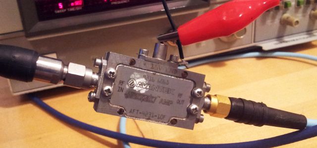
The task for today – characterization of a bunch of microwave amplifiers, Avantek/HP AFT-4231-10F. These are quite rugged and affordable components, widely available surplus, and hermetically sealed – will last forever, if things are not messed up completely.
The specification however, it’s not quite clear, and no detailled information could be found on the web. That’s why I have been asked to come up with measurements and a calculation model that allows to estimate the gain (and the actual maximum output power, and the necessary input power, to reach close to maximum output), at any given frequency and input power. Also, it needs to be checked how far above 4 GHz this device still works.
Last item is to measure the supply voltage sensitivity of the gain, to get a feeling on the required stabilization, to avoid incidental AM on the signal.
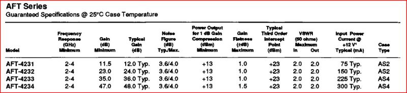
The datasheet –
The only equipment at hand at my temporary workshop here, a microwave source, EIP 928, and an HP 8565A spectrum analyzer was used to measure the gain at various input levels. Accuracy of this setup is about 1 dB.
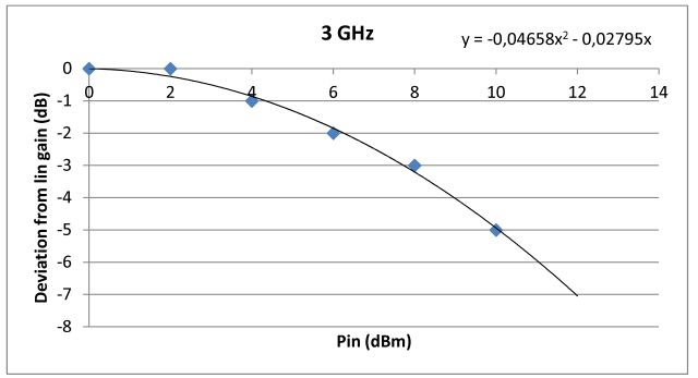
Some of the results (0 dBm input: blue diamonds; 10 dBm input: green triangles):
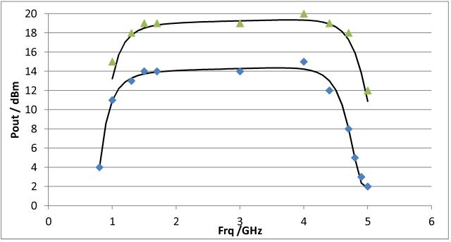
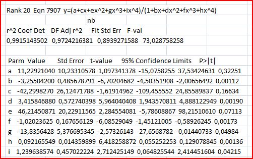
To get a proper continuous description, these data were fit to a non-linear function, fractional polynomial term (fits are done using Tablecurve 2D, an excellent program, highly recommended, but doesn’t come cheap):
The gain fit (0 dB input) can also be used to describe the maximum power, with some scaling factors – this considerably reduces the number of parameters needed, and the calculation effort later, when implemented in a microcontroller. Black lines in above diagram show the fit results.
For the gain compression, a 2nd order polynomial is used, and scaled for the 10 dBm input gain.
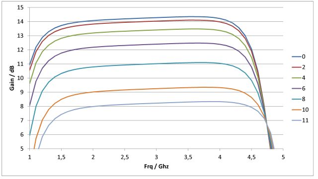
Once this is all established, no big deal to see the full picture.
Gain, at various input power levels, Pin:
Output power, Pout, at various input power levels, Pin:
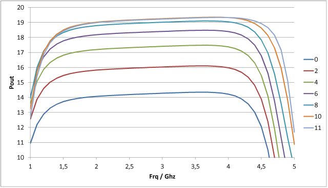
Accordingly, no problem to get 18 dBm+ in the 1.8 to 4.5 GHz range, perfect for the application requirement.
The final item – supply voltage impact on gain: tested at 3 GHz, 0 dBm input power.
Using a Micro-Tel 1295 test receiver, the reference level was set to 0 dB at 15 V supply voltage, which is the nominal voltage.
Down to 9.0 V, the AFT stays within an excellent 0.01 dB variation. Output power slightly increases (0.15-0.25 dB) down to 6 V. At about 5 V, amplification cuts out. So the AFT can work with any voltage from 10 to 15 V, at about 80 mA, and seems to have pretty good internal regulation.