
Quite frequently, I encounter rather large stacks of system power supplies and multimeters to test various types of equipment or circuit prototypes. Often, voltages are just in the 0..10 V range, sometimes, up to 40 V, at small currents. The response of the ciruit is then measured, often, after conversion to a voltage, or as a frequency, etc, with a counter.
This all works, but consumes space, a lot of power, heavy lifting, etc.
Therefore, what is needed, is a kind of Swiss Army Knife, a ADC-DAC unit, with some capable software, a small box that replaces at least two power supplies, and two voltmeters. Preliminary name: AIOM
Essentially, a small brother of the now very common source measure units, aka, “SMU”s.
Possible uses include:
(1) Test of diodes etc – trace recorder.
(2) Control of sweep generators, synthesizers, analog spectrum analyzers (most of these devices have a 0..10 V tuning-frequency control input, and often, a chart recorder-analog output, +-5 V, +-10 V, +-1 V, or similar).
(3) Test of VCO tuning curves, YIG current drivers, YTF circuits. Special VCO analyzers exist, but no need to block a whole lot of space just for some tuning test, and are too expensive to have multiple units at hand all the time. Often VCO tests need to be done at various temperatures, and over considerable time, to ensure performance of a circuit – multiple small test units will allow parallel testing, at very resonable cost.
Features:
(1) Two 0..10 V outputs, 16 bit resolution, low drift, better than 0.05%; source and sink. Needs to have reasonable low noise.
(1b) Optional, to be added, voltage to current converter (to control current, rather than voltage, 0..10 mA, source and sink).
(2) Two inputs, one referenced to ground, one fully differential +-10 V.
(3) Ramp generator and similar features (rough sine, triangle, square/PWM), in hardware, to allow fast sweeps or steps or PWM-related tests (something like a simple arbitrary function gen).
(4) While the basic design will be kept strictly unipolar, there will be a simple switching matrix, to allow polarity reversal. This will also ensure fully symmetrical tests, e.g., for charge counting-battery test, charge-discharge efficiency tests.
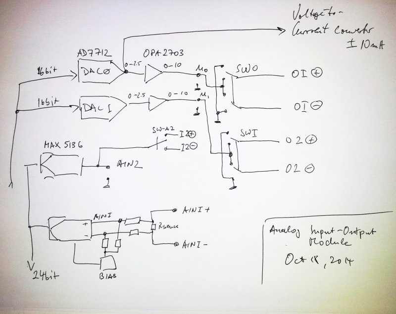
The whole little thing has two parts: the AD/DA converter board (prototype build), and a switching materix (still waiting for some parts).
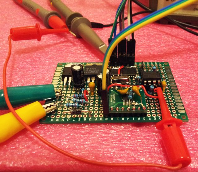
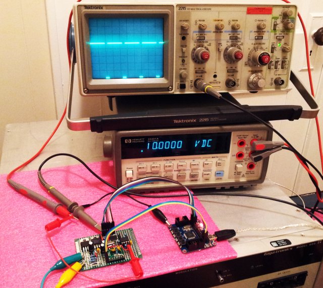
First tests successful, stay posted!
Hi Simon,
Just a little comment on your AIOM schematics…
Not very important but on the first image you have inverted the chip names: you have drawn the 7712 as the DAC and the 5136 as the ADC…
And your site is very nice and interesting, keep it up!
You are right, Thank You!