
Introduced in about 1980, the 8662A is a marvelous machine, it is an ultra-clean signal source, with very low close-in noise. This is the kind of oscillator used as a reference for phase noise tests, narrow channel receiver testing, and so on. Just a quick glance at it inner working, and it is clear that only the most brilliant engineers must have been working on this apparatus in those days. Sure enough, this did not come cheap, about 30 k$ in 1981, something like 75+ k$ nowadays…
Even more interesting, these machines are still in use today, and are still valued for the same reason – hardly any synthesized generator exists that has similar close-in noise.
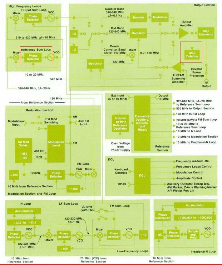
The block diagram – essentially, there are two ultra low noise switched inductor osciallators that form the reference and output sum loops, together with with some fractional and n divider circuitry, to allow for the fine resolution. The output sections has a heterodyne band, and other bands derived by doubling or dividing the 320-640 MHz fundamental output of the output sum loop oscillator.
As with all wonders and complex machine, they sometimes stop working. This one had two issues reported, inaccurate output power (and error #10B – ALC error for some frequencies/settings), and a ref sum loop unlock condition at certain frequencies. The latter issue had been persisting for some time, but the ownder didn’t use it at the critical frequencies, the ALC loop error just recently seems to have come up, for now external reasons, apparently, during a measurement.
(1) The output sum loop A6A5, error #06. This turned out to be a drift issue, of the low noise REF oscillator. This had drifted out of pretune span, and needed just very slight adjustment of the tuning screw (under a heavy metal cover, rear panel of the instrument). Such adjustment is not mentioned in the manual, but easy enough, set the generator to 640 MHz, check that the pretune is properly adjusted (adjustment is done for -3.75 V at 320 MHz), introduce a -34 V tuning voltage signal, and adjust for a frequency a bit above 640 MHz, say, 642.5 MHz, to give the phase loop a bit of room to operate.
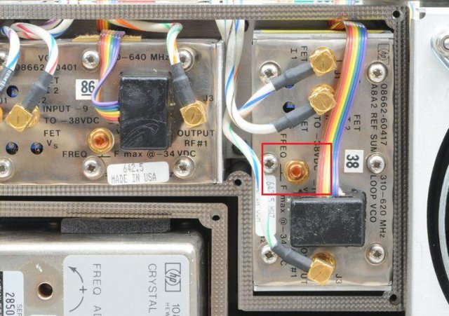
Great care must be exercised, because the adjustment uses a copper (!) screw – red frame in the above picture, most likely, acting as a capacitor vs. a metal surface inside of the unit (don’t open up these oscillators – they are wraped in Mu metal or similar exotic material). Don’t overtighten the retaining nut, copper is pretty soft.
After that, the ref loop is stable again, even when sweeping through the full band, for some hours.
(2) The more tricky part, as it turns out, the ALC loop. This is implemented on assemblies A4A1 (which has the peak detector), and A4A7, the ALC control, this has a DAC, to set the target voltage, and a regulator, to keep the output signal at the level set by the DAC output.
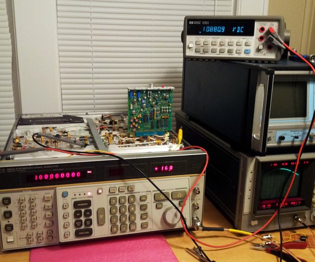
After some time of probing around, and substituting the input of the A4A1 assembly by a calibrated 100 MHz signal, it is clear that the A4A1 peak detector delivers insufficient voltage, and that the voltage is frequency dependent.
A quick glance at the schematic:
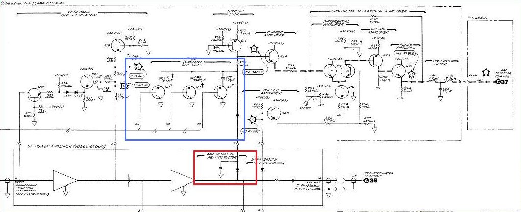
Blue frame – the bandwidth limiting circuit, enganged at below 10 MHz – first guess: something is at fault, in this circuit. Well, unfortunately,after even more probing, and even swapping some transistor (they tested good but you never know) – the focus shifted to the part in the red box. The peak detector diode! This is really bad news, because it is part of the output amp microcircuit, part number 08662-67008. Carefully desoldered, and checked – the detector diode has 0.3 V forward, which is fine, and 0.7 V backwards – this is a far too low reverse breakdown voltage. Something must have happened with this diode, maybe, it is just age. So, I openend up the circuit (the lid can be lifted off with a knife, glued on with silver epoxy), and inspected with a microscope – no obvious defect, all kind of nicely wire-bonded parts on sapphire(?) substrate – nothing I can fix with the tools at hand.
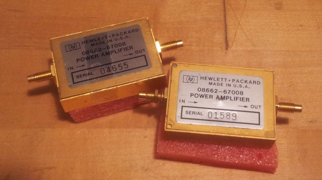
But, as luck comes along, found two of these circuits on ebay. Very mysterious. They look like old and used and ripped out of the boards (with a screwdriver, not by desoldering), and I suspected that the two might just be damaged parts – but 14 days right of return were offered, so not an issue. Even then, it doesn’t really make sense to rip the out of the board, every reasonably skilled and knowledgeable person would rather desolder them carefully, and fit a spare. However, these spare still had the through hold plated vias on the connectors, from the board. Glad the feed-throughs at the bottom of these microcircuits are so sturdy! Well, the only explanation I have – someone saw the golden parts, on some odd circuit boards, and only wanted to keep the gold, but not the boards. Fair enough.
And, this is almost the end of the story, the spares arrived within a few days, and I cleaned them up, and fitted the most “used” looking 08662-67008, and, quite to my surprise – working just fine.
The only thing that remained was the amp bias adjustment, the offset adjustement (both on A4A1) and the CW power adjustment (A4A7) – also checked the other alignments of A4A7, but they were all still fine.
In the end, still one output amp in the box, for the next 8662A, and the current one, back alive.