
The HP 8642A is the cheaper brother (or sister) of the 8642B (see here, I have two of the 8642B around and still use them quite a lot, one in Japan, one in Germany), it is essentially the same unit, but the “B” has a built-in doubler to effectively double the frequency range. The 8642A works up to 1057 MHz, good enough for most HAM purposes. It has all the desirable HP high frequency goodies inside, including, a set of precision 140 dB attenuators, and a huge number of parts that would come in handy for repair of other RF gear, everything of highest quality, low noise transistor, high reliability tantalums, a box of cables and connectors, and at least 20 kg of case aluminum. So, I did not hesitate to buy this unit for the scrap price of the aluminum contained. It also has a low distortion modulation source, which is also very useful, and has a may high quality relais and opamps.
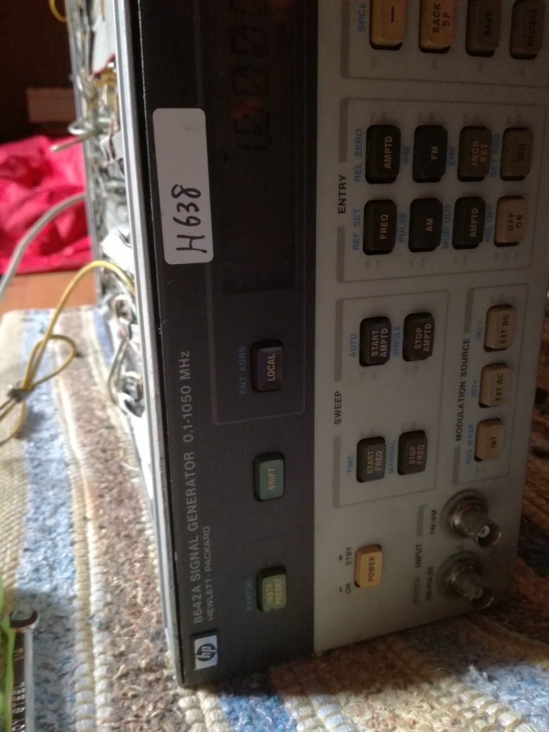
The unit is somewhat dirty, seems it had been sitting in some storage room for a while, and looking at the fan inside, it also has seen some hours of operation (which is not necessarily a bad thing).
The front frame has a mechanical damage, some part is missing – fortunately, no damage to the front panel. But I have some spare HP System II frames, let’s see.
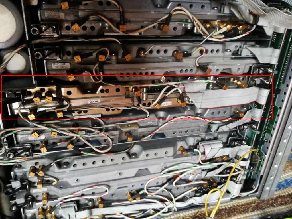
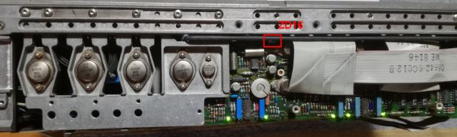
Strangely enough, one module is quite shiny, the case aluminum had some other surface treatment – also, it has a later date code (1989), compared to the other units (1985-87). Upon close inspection of the connectors there are slight scratches – seems this module has been replaced. The 8642A had a field repair program based on module exchange (even the specs were guaranteed after such exchange), quite likely that this module had failed after a couple years of service.
After a quick power up test – nothing to report, the unit is not powering up at all. Took all the panels off, and checked the voltages – nothing present. Checking around the rectifiers and capacitors – all is good here, but the voltage regulators (+-5.2 V, +-15 V, and +-50 V) won’t start up, even when I try to force them. Checked the rails – disconnected the cable (ribbon cable) from the supply assy (A17) to the power distribution board. The 15 V line has a hard 0 Ohms short!
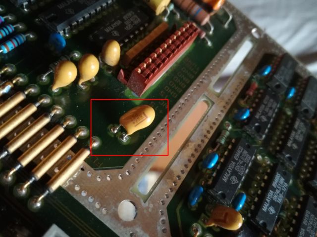
15 Minutes later – checked each module. And the shiny one has the short! A bad 10 uF Tantalum (25 V rated, running at 15 V – should usually be good enough). Replaced it with a 15 uF, 25 V Kemet – no 10 uF Tantalums here in my Japan workshop.
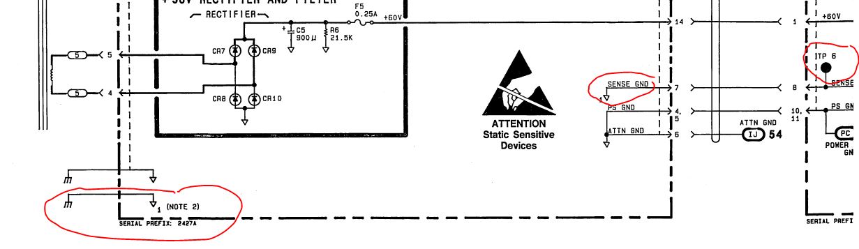
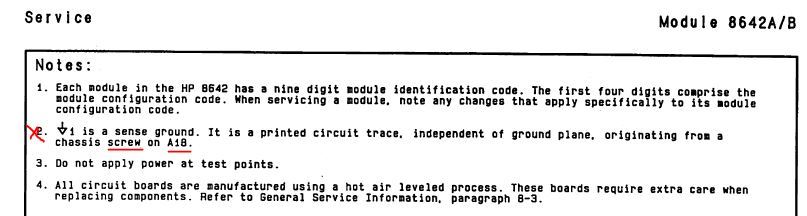
Still, before we proceed, let’s be careful with the power supply. Not that it starts up, and has some issues, and all the modules are gone. Easier said than done – there are sense wires going to the power distribution board, and, a ground sense wire going to the rectifier board (A18). I didn’t bother to study the schematic and notes too precisely, there it says: sense ground, connected to a screw and to the chassis. Of course, I had removed this screw, and now wonding why the supply won’t work…
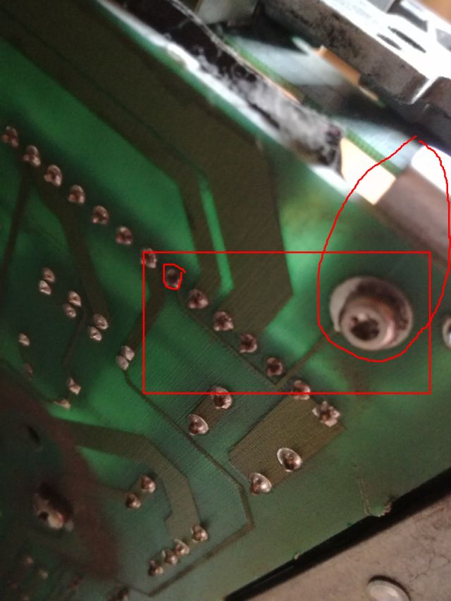
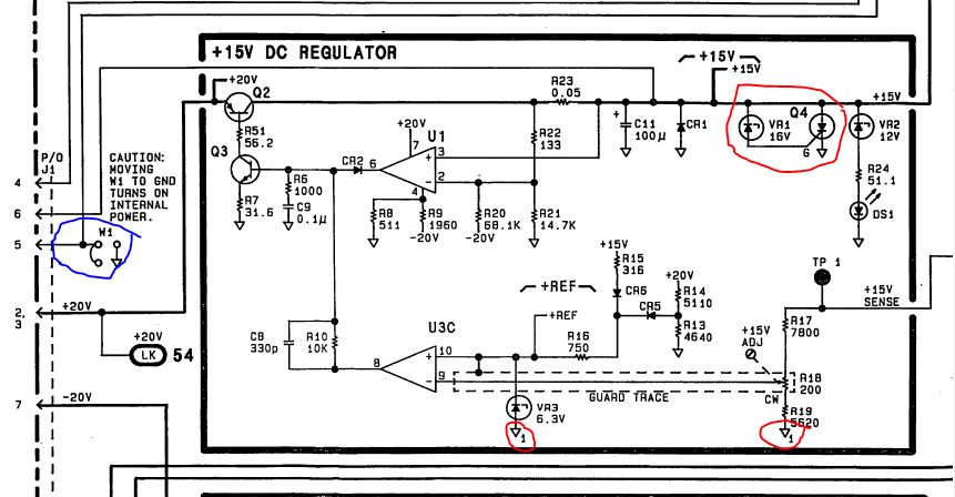
That’s how this screw and trace looks on the schematic.
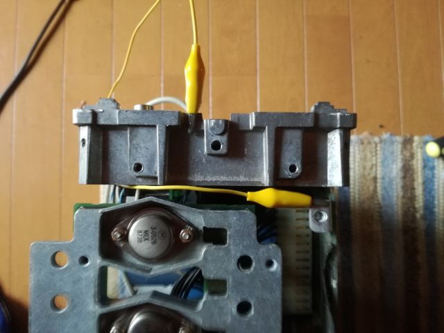
Fixed it with a jumper wire, still no success.
Fortunately, only minor trouble, a dead Zener in the 15 V crowbar (using a Zener-Thyristor-SCR circuit, marked red below). And, by design of the supply, if the 15 V is dead, all supplies stop.
After this fix, the supply is starting up, and all voltages are accurate to 5 mV, with no adjustments… this is real quality. And with the supply, the unit is starting up, and passing the start up self test, and even the extended self test (preset-shift-330-Hz), no issues.
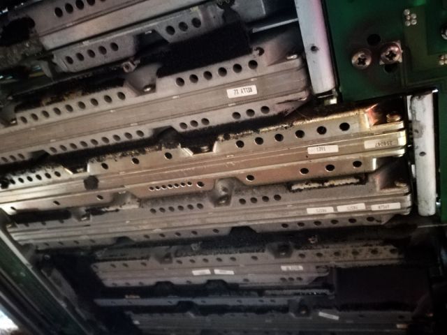
Not so high quality are the elastomeric materials used – two kind of foam, one of low density, which completly desintegrated to a black glue like substance (same applies to the 8642Bs I have, so it is a material age issue, not related to the storage or use condition). First, scratching off all the old stuff with a credit card. The bottom cover was a mess, so I don’t show pictures (couldn’t touch the camera with the gloves).
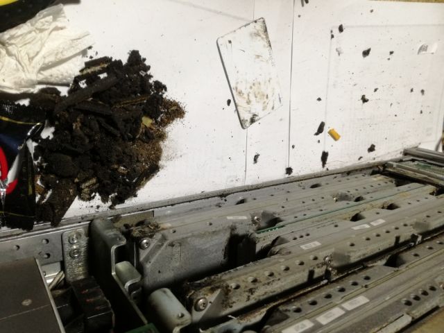
Everything cleaned off. Below, these are the craps (including a chocolate bar cover, which you will need after this messy work).
The new foam pieces (not shown), were all cut to the precise shapes, and mounted with double-side tape (carpet tape).
There will be some further repairs needed (the backlight is not working, and I need to get a good front frame from my German junk pile), but some initial tests were done. Phase noise is good, at least as much as I can check, vs. a 8662A, tested at some random frequencies (10 and 56-odd below).
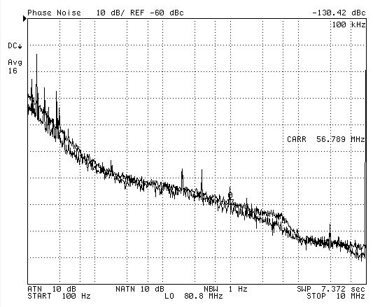
Note, at above 10 kHz, the 8662A has higher phase noise than the 8642A, so the test can only show the overall function and absence of phase noise issues (for the 8642A) above these frequencies.
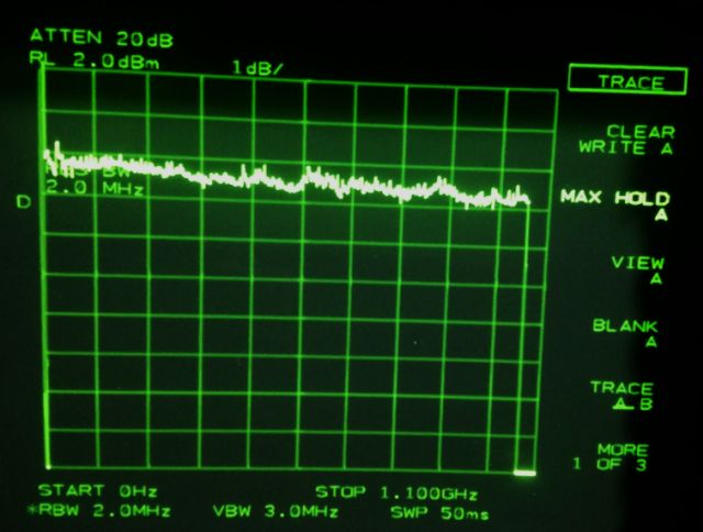
There are issues with the attenuators. And flatness, see below. Even with a rather crude spectrum analyzer as flatness indicator, all within 1 dB easily, over the full span.
All in all, still a good unit, and I won’t yet use it for parts and spares.
hi Simon,
Did you ever try to upgrade an A model to a B model?
No, I don’t believe it is possible, there would be a need for exchange of assemblies, a doubler etc. May not be worthwhile. I have two B model and on A model generators.
Simon
Thank you!
Just diagnosed my A model as having a bad 33321S option 15 step attenuator 🙁 I took it out and put in a shunt SMA cable for the time being. At least I can now test the other functions.
But what to do with the dead atten.. hmm..
Wilko
NB: I second your thoughts on the engineering. No cost or effort was spared. Amerikanische Grundlichkeit vom Feinsten!
The attenuator, you can actually try to fix it. The model should be SG SC SD or similar. Does it just say S? Defect can be blown pads, but most often some issues with the contacts.
It indeed just says S. I have 2 different attenuators in the unit, an Option 15 and and Option 75. Interesting.. have not found docs on these yet.
In the meantime I have opened the failed attenuator. And, surprise surprise, it had exactly the same failure mode as you reported in your article about “broken spare”. So, the metal contact had come loose from the gray plastic insulating support. It was literally rattling around. 🙁
Now the question is: would 2 component epoxy glue be adequate to keep in mounted on the gray plastic support….?
oh.. forgot to mention: it is the contact that connects to the SMA connector
I think it will not be a very permanent repair to just glue it to the surface because of the flexible nature of the spring. If you have precision tools you can drill two holes into the plastic – where the broken off plastic pieces were located and glue in small plastic rods with retainers. Or just use plenty of glue all around, glue it to the sides and above, it wont be a good SWR but probably good enough for the frequency range. These particular attenuators come with many parts numbers but are the same internally. The 15 volts type in the 8642a/b is fairly common sometimes you can get these for 40 usd on ebay.
Well, exactly, the springy spring has me worried too..
Have you managed to get the old resin off the spring? I mean the stuff used to keep the spring attached to the now-broken plastic pins. If you cannot get that stuff removed there is little point in the drilling exercise?
It is a while back but I think the glue including the broken off plastic parts came of quite easily after heating the thing on a hotplate a little.
Thank you, that probaby implies that heating it with my hot air soldering equipment will also do the trick for removing it.
What kind of replacement plastic pins were you planning on using? The diameter is minute, while at the same time the spring contact might excert quite a bit of force (well, given the tiny pins I mean)
Soldering iron may also work but take care not to contaminate with solder. I used Nylon rods, these are pretty stable on pulling force. I just pushed them into holes and made the size fit well on a lathe.
Solder would indeed ruin your whole day.
So if I understand correctly you took the gray plastic block, drilled two minute holes where the now broken pins used to be, then glued in place two new Nylon rods? Subsequently the Nylon rods are fed through the holes in the spring and fixed with say epoxy 2 component glue.
Hmm.. I do have a lathe but not one suitable for this tiny stuff.
Maybe Nylon fishing line, or the line used for necklaces etc can be used? Comes in various diameters and is strong.
That’s right. Drilled holes pushed i rods then the spring then added a small washer made from some plastic with tight fit on the nylon and then glue. Sure you could use some nylon wire but I would treat it with sandpaper beforehand to make the glue stick.
OK, thank you. Given the diameter of the rods a watch makers lathe is required, which I do not have. Advantage of turning the pins is that the pins are a bit rougher than fishing line, so better adhesion to the glue.
Did you remove the gray blocks from the attenuator housing before drilling?
I just turned it on a regular lathe from 6 mm stock or similar. I drilled it inside. But you can remove the while pastic strip if you take out all the coils and so on. Not recommended if you dont need to.
In order to record the info for posterity:
I just got the broken bits off the spring with hot air. 200degr C and within 10 seconds they came clean off. No residue, just clean.
So stay away from a normal soldering iron for this procedure, this is my prefered way.
Good news: the attenuator appears to have been fixed! I took a slightly different approach, a bit difficult to explain. I do have made quite a few pictures, more than happy to send them to you.
Please advise on email address to use.
Wilko
That’s indeed great news. Please send. Simon at simonsdialogs.com
I hope the photos made it in good order. Sofar the attenuator seems to keep working as it should. Keeping my fingers crossed!
Next challenge is to find a set of the original feet. It was used rackmounted so it came without feet 🙁
Yes, Thank You. I will put some online here if you dont mind. The feet, they are available from ebay but not cheap. There are two shades of gray, the older instruments are a brownish gray, the newer ones pure gray.
Please feel free to use the photographs. Might be useful to others. Would not do it this way for say a 26GHz attenuator but at 1GHz this minute piece of FR4 PCB material does not hurt. I considered using some PTFE/Teflon but glueing that…