
With some success, and power supplied at proper voltages to all assemblies, we can get into the inner workings of this marvelous unit. There are issues, all kinds of UCL messages and E-07 during calibration. Connected a 1 kOhm resistor as a test device, and played around with the ranges and frequencies, and some luck – at 1 kHz, and with manual range selected, I do get a proper measurement (but not in the other ranges), at higher freuquencies, no measurement possible, the bridge is not balancing.
So, let’s take it step by step. First we need to check the source assembly, A1, or part of it – quickly found out that the supplied voltages and source resistor switching (by mechanical relais, therefore it is a good place to check – but difficult to fix, because there is all kinds of magic around these relais to eliminate parasitic capacitances – you can’t just put in any ordinary spare part). All is good with the source assembly.
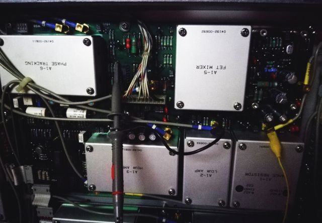
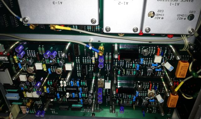
Also the inital stages of the receiving section and the mixer, working fine. These circuits are part of the so called process amplifier, A11 assembly. The whole input circuits, please be careful, there are many precision parts and FETs and expensive things – don’t damage it. And it is pretty complex, so don’t get lost.
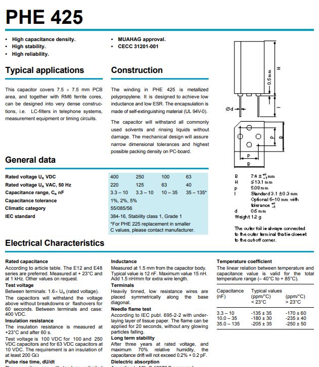
Along the way, an interesting part, a RIFA precision PHE425 cap.
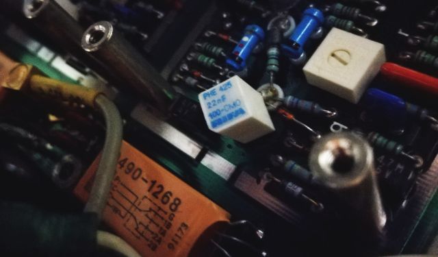
The “F” in 22nF is not actually Farad, but the tolerance denominator of Rifa, meaning, 1 % tolerance. The caps have very good data, very low drift over time, and a very low voltage and temperature coefficient. Maybe I will consider these for own designs, filters, and so on.
Testing, and testing again: found an issue with the IF amplifier – it is not switching the amplification properly, it is overly amplifying the signal (locked in x10 mode). No wonder it doesn’t work at high frequencies as it will saturate the following circuits.
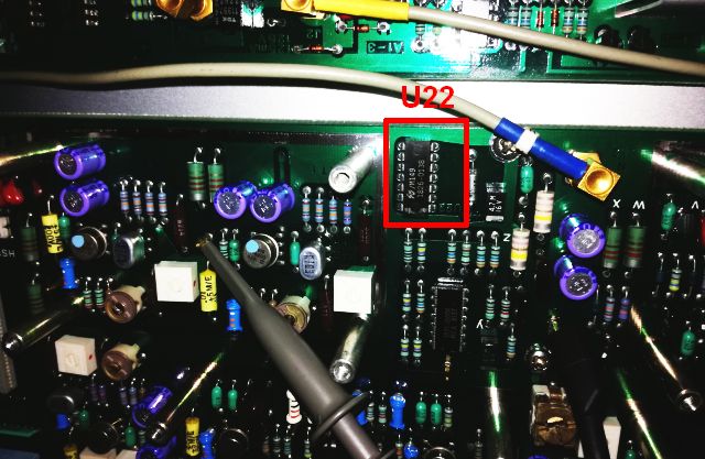
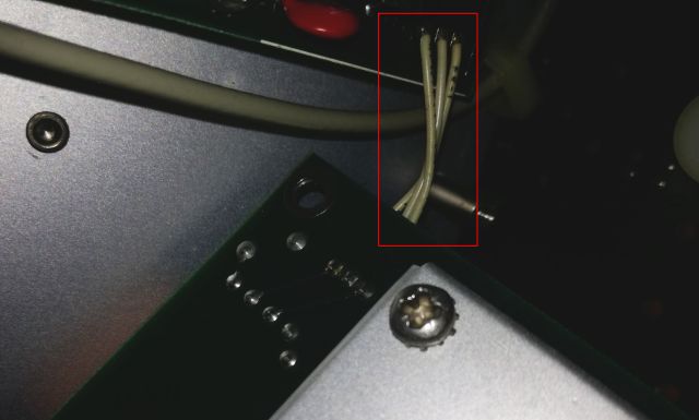
The A11 board, it is not as service-friendly as usual, because it is connected to the A1 board by 3 wires that are soldered to the board, in a narrow space (no plug!).
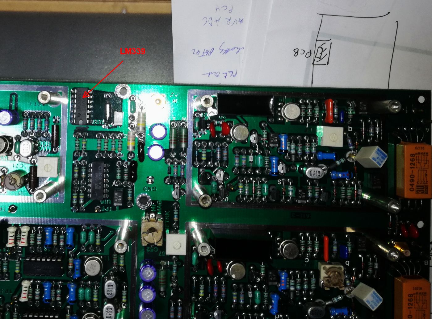
In the block diagram, you can clearly see the x10 and x100 amplifiers.
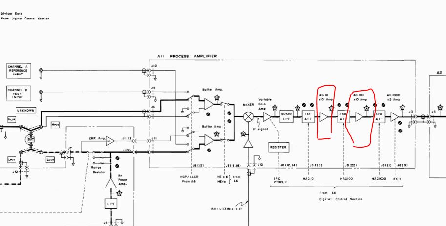
These are controlled by a quad comparator that is set by the controller assy.
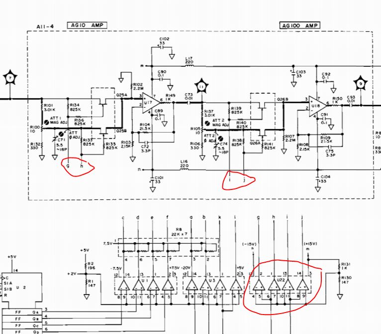
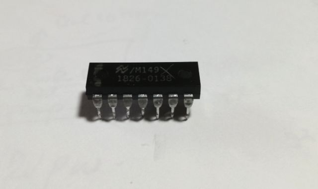
Some LM339’s are in stock here, it is one of the most essential parts to have in any electronics workshop. The LM339 is the equivalent to the HP 1826-0138. It is run at over 30 volts supply (-16 to +16 V), maybe it got damaged during the power supply failure and some related surges. But the 1826-0138 HP parts are also known for some age-related failure, at least I have already replaced a few others in HP instruments.
The bad part – causing all the trouble.
Quite some extensive tests later, I decided to put the instrument back together (many of the shields still removed), and had it run for a day with no problem. Self test and calibration is working at all frequencies. Adjusted the phase balance, the amplifiers and attenuators according to the manual’s instructions. Adjusted the power supply after due warm up. Not much adjustment needed. The bias supply, it is as good as the test equipment I have here, will need to do some tests later in Germany with some better voltmeters.
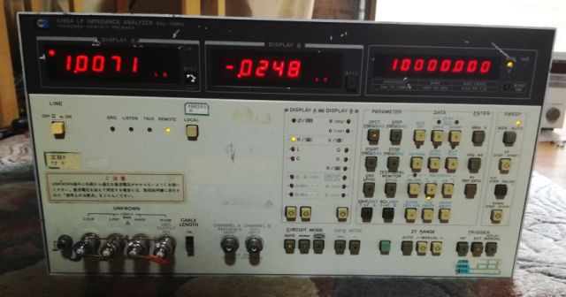
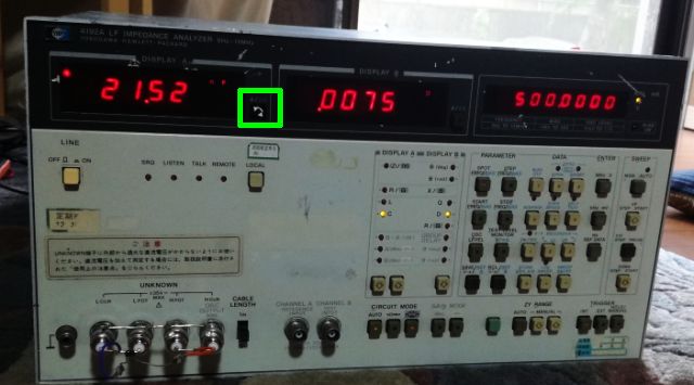
Some test measurements – using a 1 kOhm, and a 22 nF capacitor.
Also, still needed from the stockpile of HP spares back in Germany – a push button cover (the switch itself is working).
These are great pieces of test kit if you have the space for them, their have a hugh footprint, but well worth the time to bring back into service. I’ve had one for a few years now, like yours it had suffered a battery leakage while in storage, the fumes attack different metals at varying rates and lead and tin plate seems very susceptible, luckily much of the exposed PCB traces are gold plated.
When I was fault finding I found it helpful to think of the machine in two parts, ie if you terminate the A& B inputs and set the machine to voltage and phase measurements you have divided the machine in two…..
All the analogue boards have decrect +- voltage regs for each stage, prob to maximise the isolation between stages, I had quite a few TO92 size regulators with poor regulation, I suspect from a previous over voltage failure.
Im enjoying reading the blog, I recall the time I spent working on my 4192A….
Fortunately, space is not the issue here, and I rather like the open design, so at least you can access the circuits and fix it without having everything micron size. I took precautions with the new battery, hope it will be leak proof. I was lucky that the digital section and the source is working fine. It is no fun to troubleshoot the fractional N board, or the CPU board. What I don’t have yet are the ROM images, did you ever backup the ROMs?
No sorry I didn’t backup the rom’s, but I think there might already be something online, have you searched in the forums? I had some faulty ram chips and GPIB interface controller, luckily they were still some available, its a fight to keep these machines up and running, but they are great pieces of kit.
Theres some excellent software for this machine posted here.
http://mkelzenb.caltech.edu/software/4192A/
I will do a ROM backup once back in Germany (no EPROM reader her in my 2nd residence in Japan), nothing found online so far. Thanks for the software link, I have used it earlier today and it is working fine. I have in mind to characterize some capacitors and semiconductors vs. bias voltage (to replace a setup using a 4277A), so probably I will write a small (console) script myself to gather such data.
Immediately checked all the 78Lxx and 79Lxx regulators, all good. Some are a bit more negative, like -12.2 V and -15.2 V, but stable.
That rings a bell, I had a neg rail that looked ok but in fact wasn’t regulating, it was the last fault I took off the machine, the symptom look like a leakage fault on the input to an op-amp or perhaps the opamp itself, it wouldn’t hold its null voltage, someone had lifted the signal clipping diodes etc, looked like it was a long standing fault, if you get it all up and running but can quite get it in spec, be worth looking at these small regulators again, they can fail and still look ok to an initial voltage check.