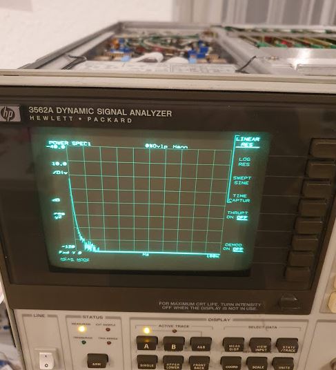
Recently, during some phase noise measurements, my 3562A failed. This instrument is an essential part of the noise test set, it is used for all frequency offsets up to 100 kHz, and as a signal/noise source (the 3562A has a fairly capable built-in noise source, signal source, etc.).
While the communication via GPIB went well and I could still complete the test job, the CRT went dark with no sign of life. I also have a second unit, with a LCD display, but the 3562A of the phase noise test set still has its original CRT. Let’s hope we can fix it because I don’t want to invest in a new LCD or anything for this purpose.
So I opened up the box (fortunately, it is accessible on top of the test set which is a stack of instruments, maybe 250 kgs of electronics), and did some checks. As it turns out, one of the rails of the CRT driver boards is down.
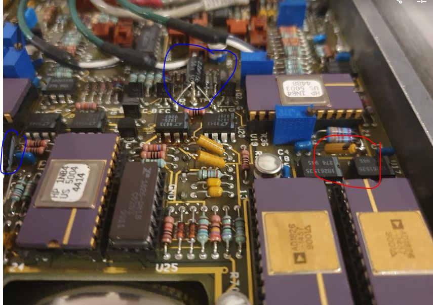
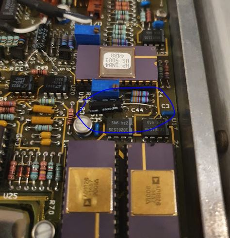
Some years back I had already replaced some tantalums, maybe some more of these have gone bad? So I cut some wires at suspicious capacitors – you can normally do this no problem, because the instrument will still function even with some buffer caps missing.
In fact, after the 3rd cut, the rail came back. The tantalum had a full short but no sign of smoke or heat, probably, because of various protection circuits of the power supply.
Replaced it with a similar electrolytic cap, probably this will do. It is a question of repair philosophy, should you replace all tantalums in such device, if you found two defective caps? I decided not to, because the fix every 5 years is easy enough, and there are just too many tantalums in it, moreover, I may break some contacts or cause issues with electrostatic discharge. For the current repair, I didn’t even remove the board, just cut the capacitor from the top and solder the spare back, from the top. As some old laser engineer told me once, the less you touch it, the better it will work. Sure enough, if the objective is to bring the unit back to the best state of reliability, it would be best just to replace the whole CRT by a new LCD assembly, or by a few 100 USD worth of KEMET high-rel tantalums and do a 5 hour solder and disassembly/assembly job…


