HP 8642A Signal Generator: To be, or not to be a parts unit

The HP 8642A is the cheaper brother (or sister) of the 8642B (see here, I have two of the 8642B around and still use them quite a lot, one in Japan, one in Germany), it is essentially the same unit, but the “B” has a built-in doubler to effectively double the frequency range. The 8642A works up to 1057 MHz, good enough for most HAM purposes. It has all the desirable HP high frequency goodies inside, including, a set of precision 140 dB attenuators, and a huge number of parts that would come in handy for repair of other RF gear, everything of highest quality, low noise transistor, high reliability tantalums, a box of cables and connectors, and at least 20 kg of case aluminum. So, I did not hesitate to buy this unit for the scrap price of the aluminum contained. It also has a low distortion modulation source, which is also very useful, and has a may high quality relais and opamps.

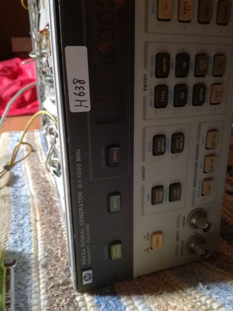
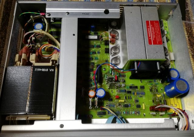
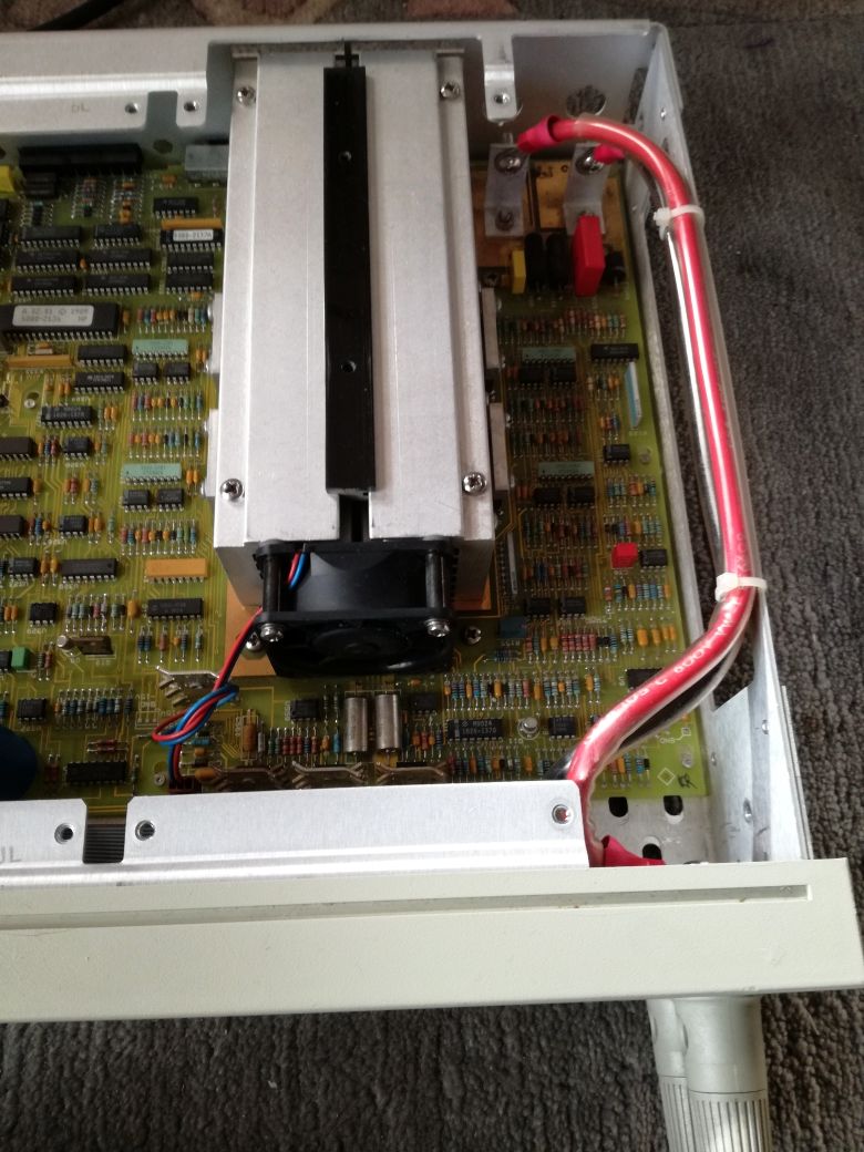
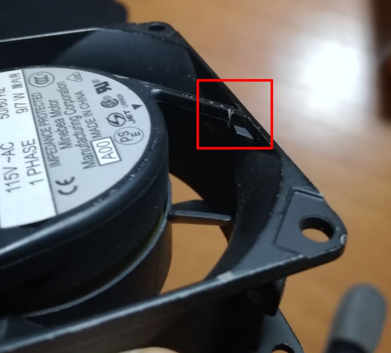
The unit is somewhat dirty, seems it had been sitting in some storage room for a while, and looking at the fan inside, it also has seen some hours of operation (which is not necessarily a bad thing).
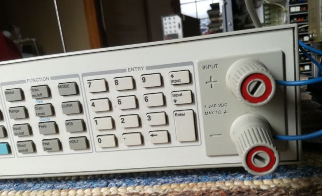
The front frame has a mechanical damage, some part is missing – fortunately, no damage to the front panel. But I have some spare HP System II frames, let’s see.

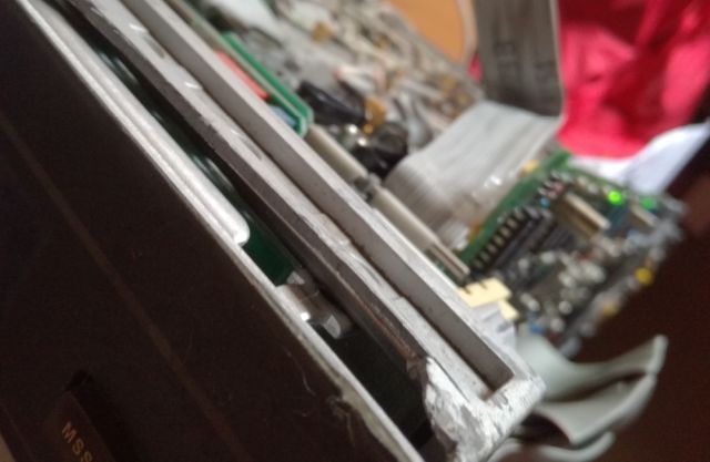
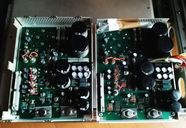
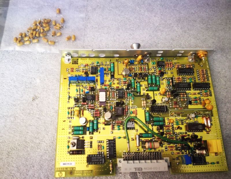
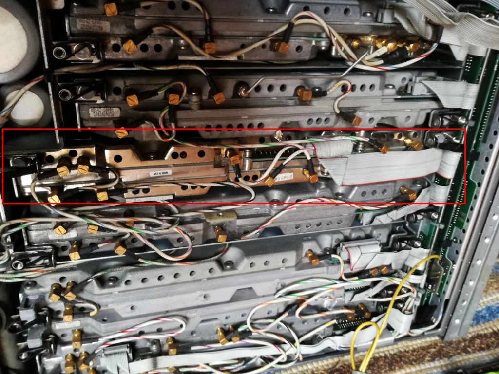
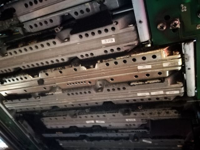
Strangely enough, one module is quite shiny, the case aluminum had some other surface treatment – also, it has a later date code (1989), compared to the other units (1985-87). Upon close inspection of the connectors there are slight scratches – seems this module has been replaced. The 8642A had a field repair program based on module exchange (even the specs were guaranteed after such exchange), quite likely that this module had failed after a couple years of service.

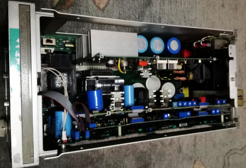
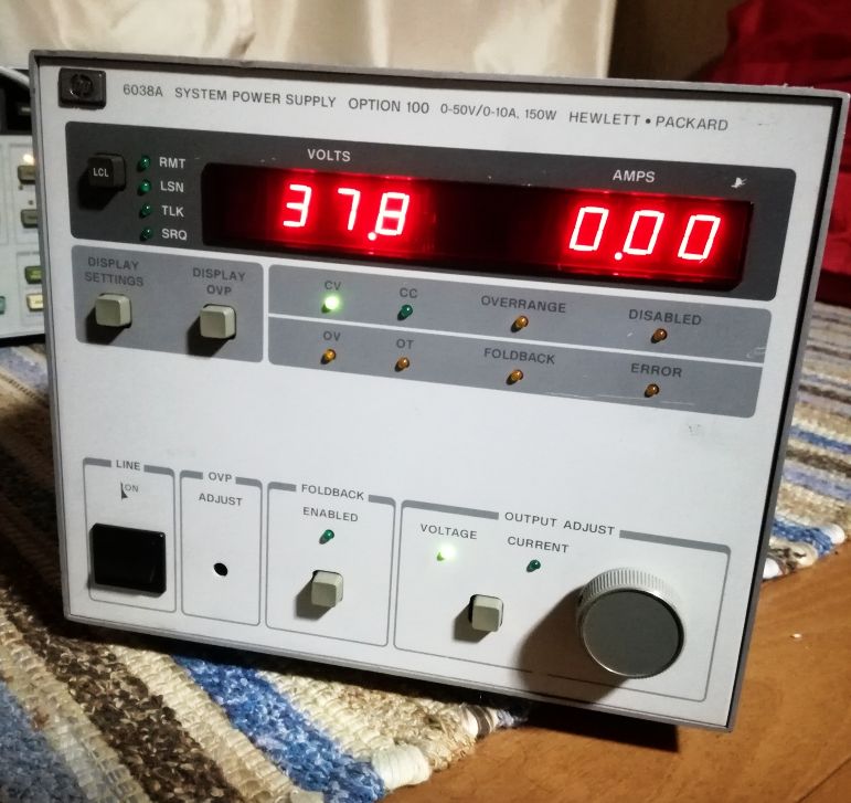
After a quick power up test – nothing to report, the unit is not powering up at all. Took all the panels off, and checked the voltages – nothing present. Checking around the rectifiers and capacitors – all is good here, but the voltage regulators (+-5.2 V, +-15 V, and +-50 V) won’t start up, even when I try to force them. Checked the rails – disconnected the cable (ribbon cable) from the supply assy (A17) to the power distribution board. The 15 V line has a hard 0 Ohms short!

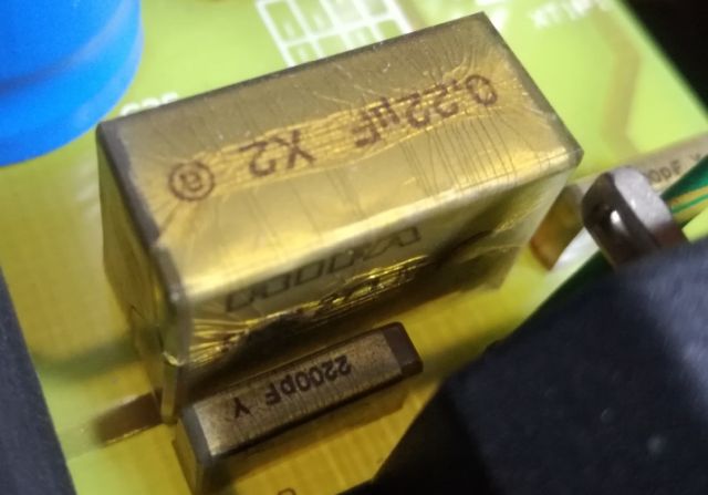
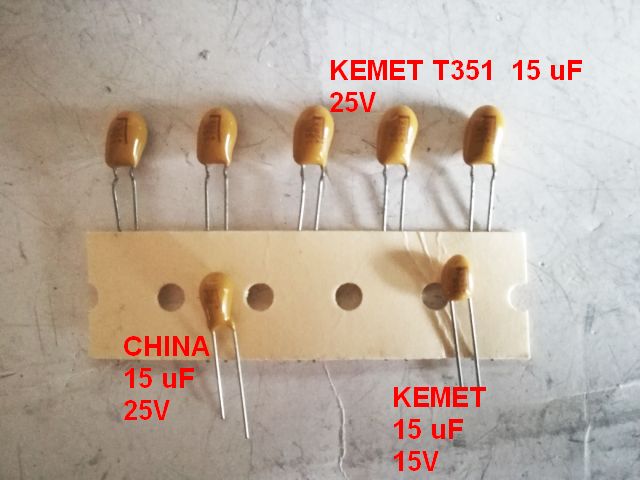
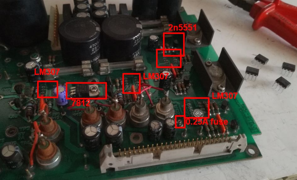
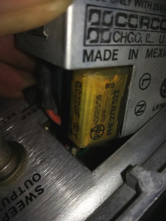
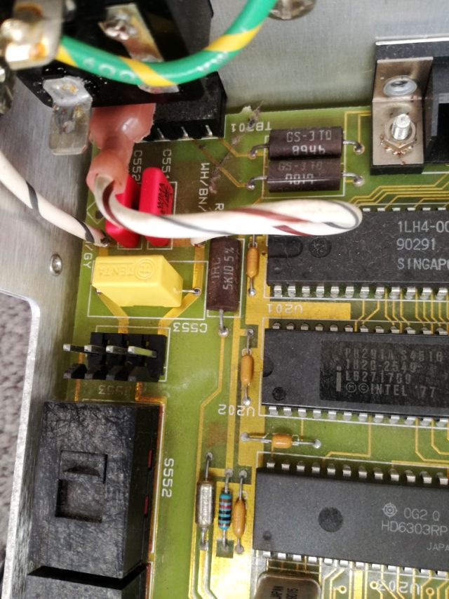
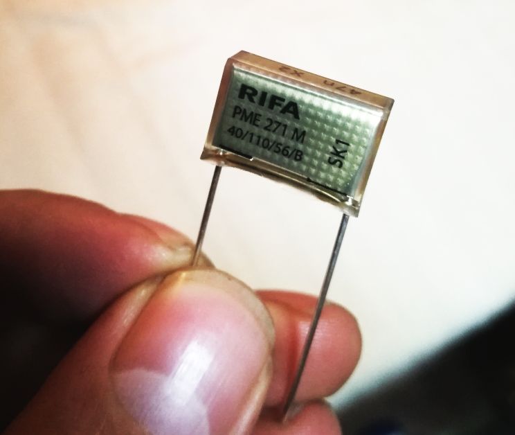
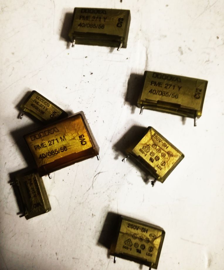
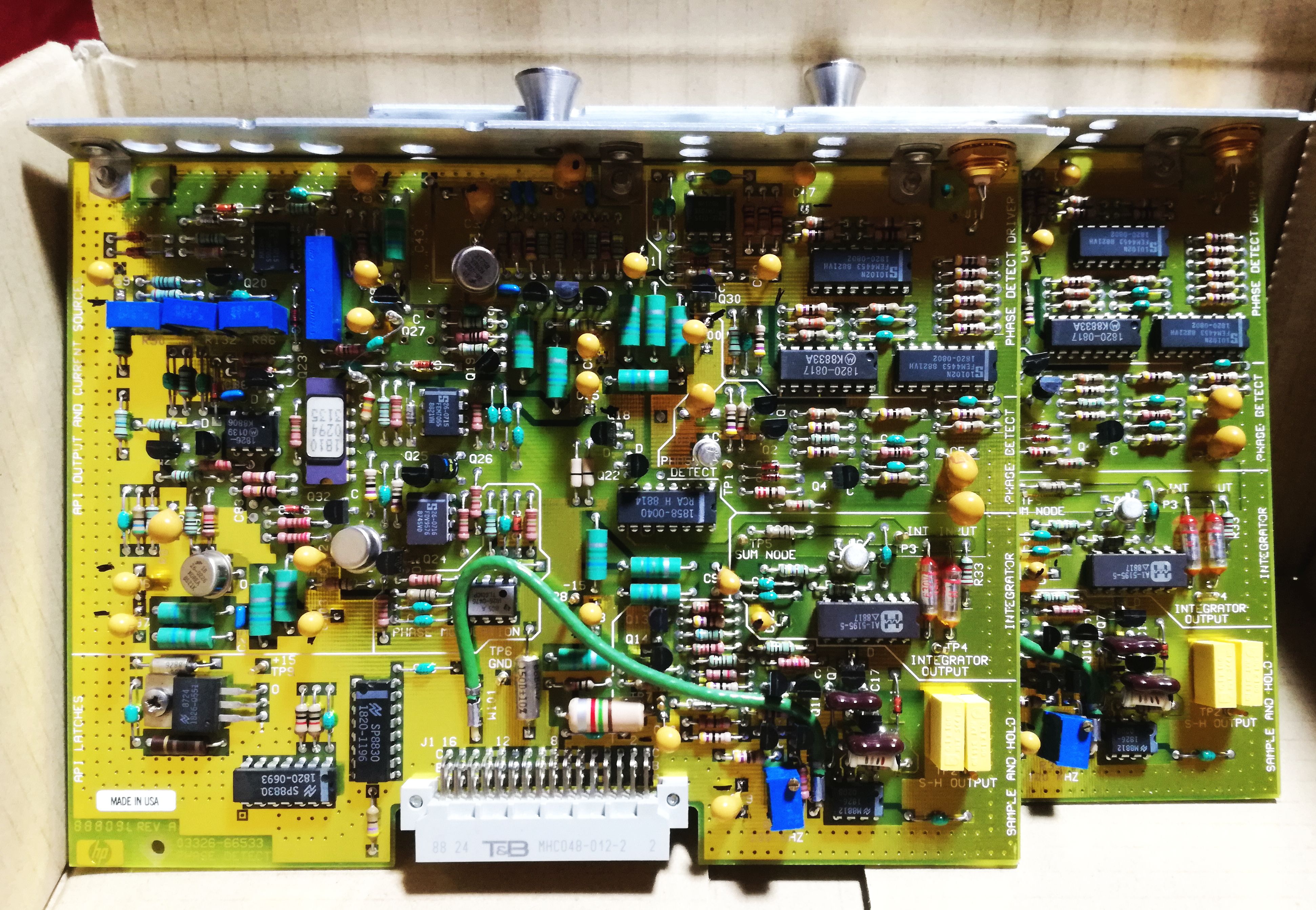
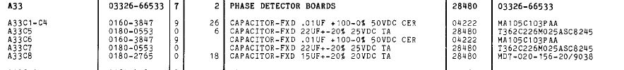
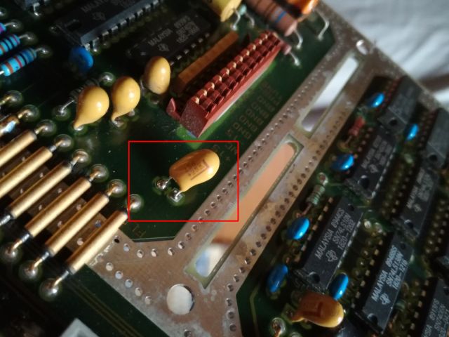
15 Minutes later – checked each module. And the shiny one has the short! A bad 10 uF Tantalum (25 V rated, running at 15 V – should usually be good enough). Replaced it with a 15 uF, 25 V Kemet – no 10 uF Tantalums here in my Japan workshop.

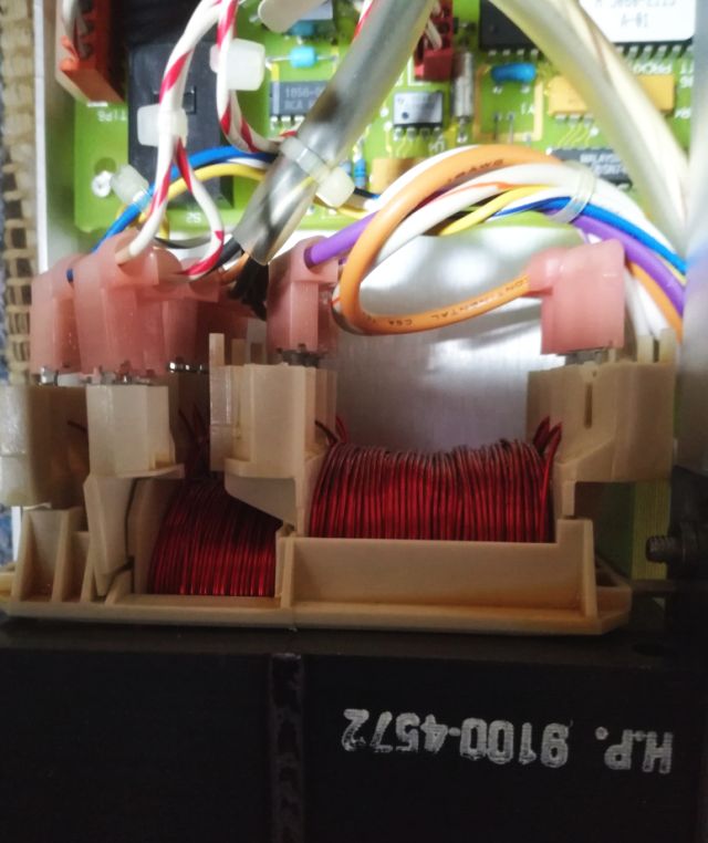
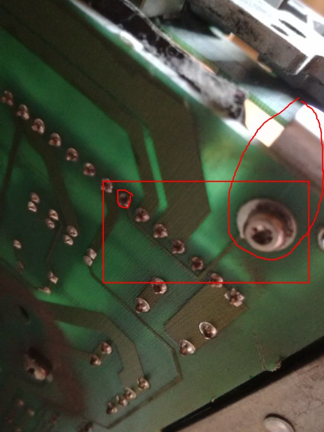
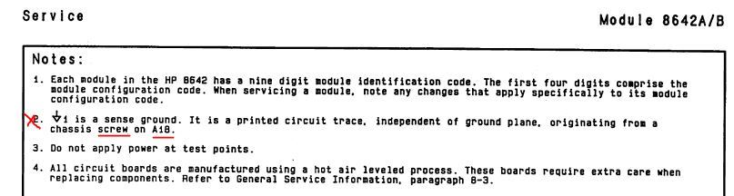
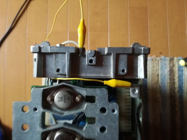
Still, before we proceed, let’s be careful with the power supply. Not that it starts up, and has some issues, and all the modules are gone. Easier said than done – there are sense wires going to the power distribution board, and, a ground sense wire going to the rectifier board (A18). I didn’t bother to study the schematic and notes too precisely, there it says: sense ground, connected to a screw and to the chassis. Of course, I had removed this screw, and now wonding why the supply won’t work…

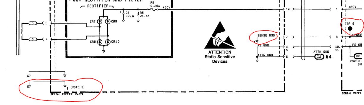
That’s how this screw and trace looks on the schematic.

Fixed it with a jumper wire, still no success.

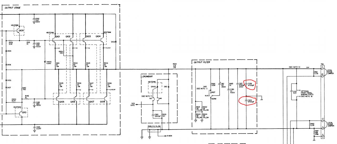
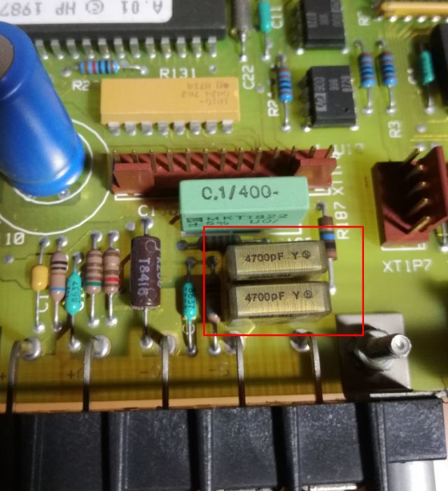
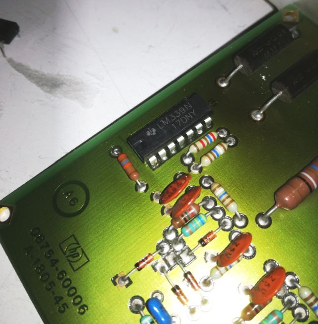
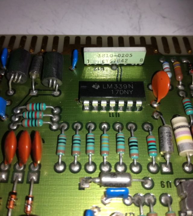
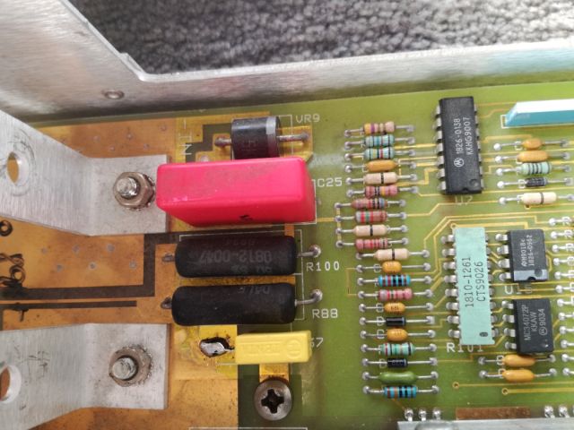
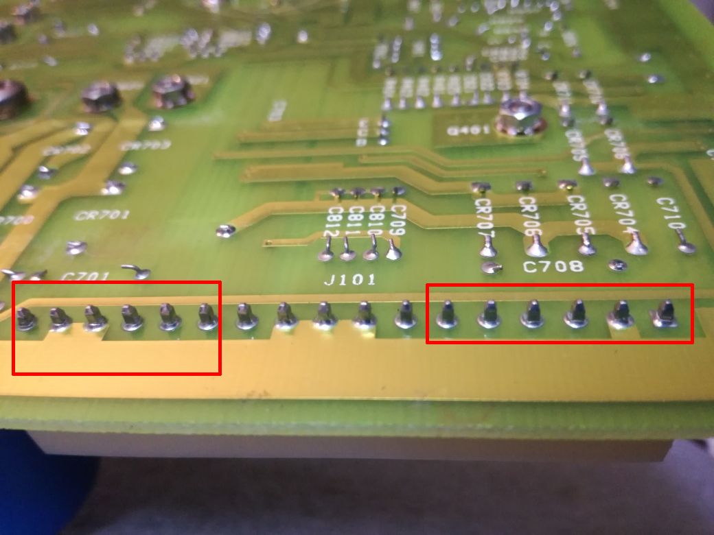
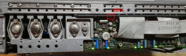
Fortunately, only minor trouble, a dead Zener in the 15 V crowbar (using a Zener-Thyristor-SCR circuit, marked red below). And, by design of the supply, if the 15 V is dead, all supplies stop.

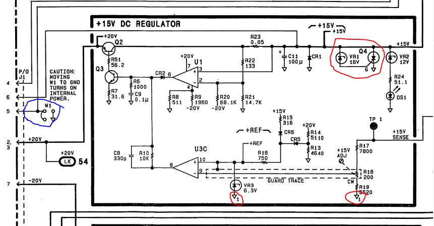
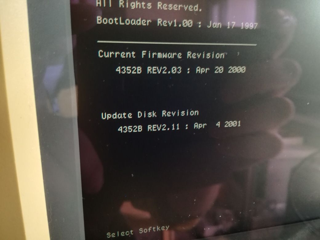
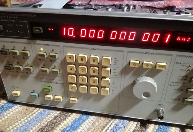
After this fix, the supply is starting up, and all voltages are accurate to 5 mV, with no adjustments… this is real quality. And with the supply, the unit is starting up, and passing the start up self test, and even the extended self test (preset-shift-330-Hz), no issues.

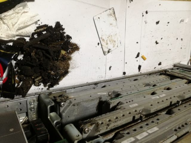
Not so high quality are the elastomeric materials used – two kind of foam, one of low density, which completly desintegrated to a black glue like substance (same applies to the 8642Bs I have, so it is a material age issue, not related to the storage or use condition). First, scratching off all the old stuff with a credit card. The bottom cover was a mess, so I don’t show pictures (couldn’t touch the camera with the gloves).

Everything cleaned off. Below, these are the craps (including a chocolate bar cover, which you will need after this messy work).

The new foam pieces (not shown), were all cut to the precise shapes, and mounted with double-side tape (carpet tape).

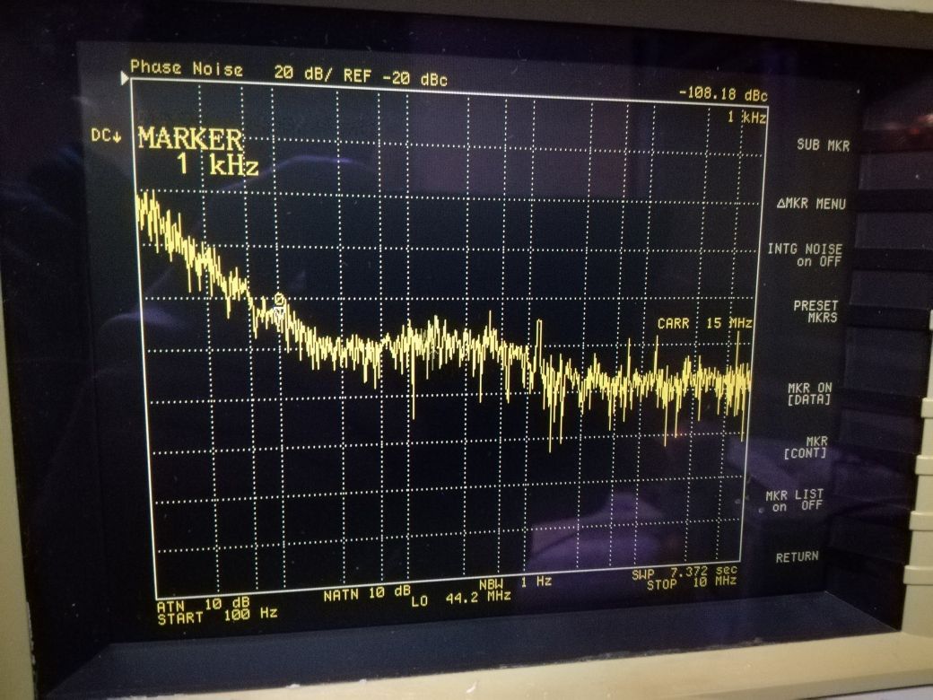
There will be some further repairs needed (the backlight is not working, and I need to get a good front frame from my German junk pile), but some initial tests were done. Phase noise is good, at least as much as I can check, vs. a 8662A, tested at some random frequencies (10 and 56-odd below).

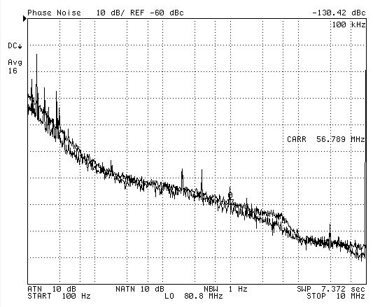
Note, at above 10 kHz, the 8662A has higher phase noise than the 8642A, so the test can only show the overall function and absence of phase noise issues (for the 8642A) above these frequencies.

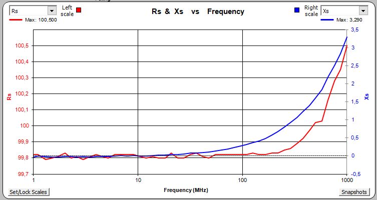
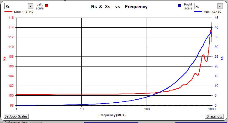
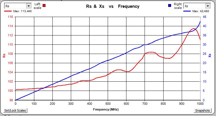
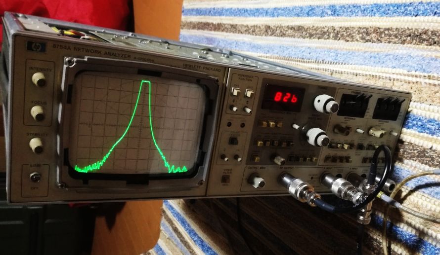
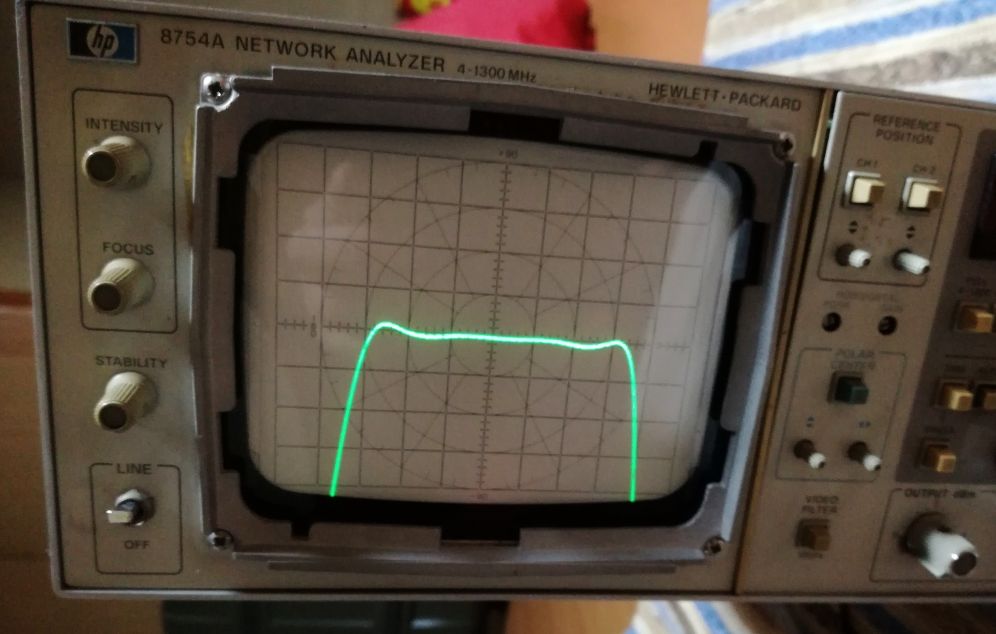
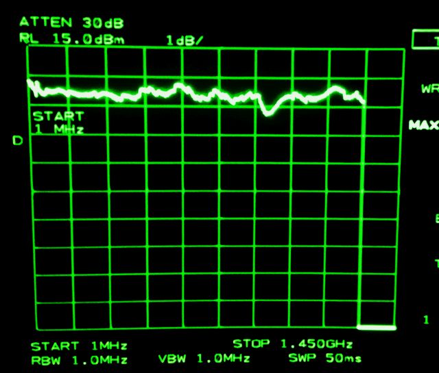
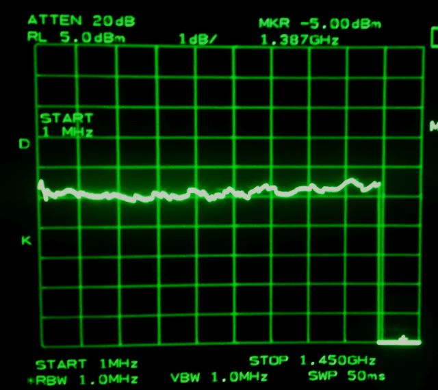
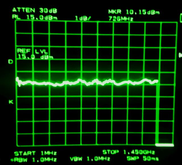
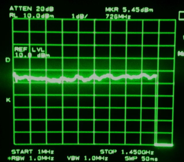
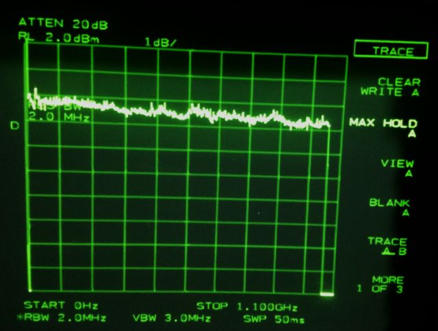
There are issues with the attenuators. And flatness, see below. Even with a rather crude spectrum analyzer as flatness indicator, all within 1 dB easily, over the full span.

All in all, still a good unit, and I won’t yet use it for parts and spares.

HP 6634A System Power Supply: A few almost-bad RIFA caps, and a 100 Volt, 1 Amp, source-sink supply, and a generous load of transistors

A quick look at a really nice piece of kit, a 100 V, precision regulated power supply, can be floated to +-240 V, and can provide 100 Watts of power, or sink power, about the same range.

The front panel and handling is like any other HP system power supply from this era, and there are models 6632A (20 Volts) and 6633A (50 Volts) that share virtually the same control circuit. All is GPIB controlled, of course, and this unit has front and read outputs. I am going to use it for a capacitor tester (to study the voltage bias effect and hysteresis of ceramic capacitor materials), so I need a fairly reliable unit because it will run unattended for a while.

The top view, there is a massive heatsink, for 100 Watts of dissipation…

The transformer, it is the highest standard and insulation I have ever seen.

There are 8 power transistor, in a really massive output stage (4 complementary pairs, 2 each on each heatsink-the heatsink is sub-divided in two sections), each of them capable of handling 250 Watts of dissipation.

The output stage, it is a really generous design, considering that this is a 1 Amp supply (most designers would handle it with two transistors).

The only thing I don’t like about the unit, the RIFA X and Y rated caps. These are all cracked (still not shorted, but I don’t want to take a chance). So these will need to be replaced.

Otherwise, all is good with this unit, almost no dust inside – I believe this instrument had very low hours, or has been used in a very clean environment (not even a trace of dust on the fan).

HP 3326A Two-Channel Synthesizer: replaced, and replaced again!

Recently, two assemblies of a non-working HP 3326A were fixed by replacing their 15 uF tantalum caps – a good number of them had failed, presumably, because of a bad production lot of these capacitors (see earlier post)

Unfortunately, during the test run, some sporadic failures of the power supply, with overcurrent indication flashing. Then, permanent failure of the -15 V rail – as it turns out, by a short in the assemblies we had just fixed! An again, a discolored tantalum capacitor. Replaced it, and a few hours later, the same issue, with another capacitor of the same kind.
My mistake, I had use a bag of cheap China-sourced 15 uF, 25 Volts dipped tantalums, but these seem to be no good (unlike other Chinese electronics good that have attained good quality in recent years, provided you don’t by the cheapest kind). Maybe it was my mistake to buy the cheapest tantalum capacitors, but not much choice if you need 34 pieces to fix some old equipment – I don’t want to pay EUR 1.45 each from top brand parts from Mouser or similar sources.

With some luck, I found reasonable prices KEMET T350 series Ultradip II capacitors, these are known to be reliable.

You can see the size differences – the KEMET part is much bigger than the Chinese 25 Volts part – it is more similar in size to a 15 Volts KEMET part. Probably, the design was put a bit to the limit.

With the capacitors replaced and another 48 hours of run in test – no issues at all and the 3326A can be considered fixed and working for now.

HP 4191A Impedance Analyzer: power supply fixed

In a recent post,HP 4191A, I have introduced a 4191A with defective power supply. In the meantime, a spare power supply regulator assembly arrived, and the repairs of the originally fitted, defective supply have been completed.

First, some research into the HP p/n 1826-0043 Opamp, which is considered to be a LM307 comparable part. But what is acutally inside the can? Let’s crack it open.

The die has a small marking, reading “LM107C”. The LM107 is very similar to the LM307, except for a wider temperature range, and somewhat extended power supply limits. In the current application, we can safely drop in LM307N opamps. It is also clearly visible that there are no bonds for external frequency compensation (like for the LM301).

The replacement power transistors have been discussed in the earlier post, and now all has been cleaned and new heat conducting grease added.

All the replaced parts marked, after all, I should have also replaced the fuses and fuse holds which show signs of corrosion and bad contact.

A quick test, on the 4191A, left hand side is the working spare, the right hand side, the repaired original supply. I didn’t connect it to the 4191A board, but just to the transformer to confirm the basic working condition without putting the 4191A to any dangers – the repaired supply with but just a spare, and probably it will never be needed… at least not for this unit.

There were no other defects with the 4191A, and now some tests with the 4191A working instrument. It is essentially a very precise one-port vector network analyzer, with a thermostated reflection bridge and some other features that make it suitable for component measurements. There are some (expensive) HP test fixtures, but essentially, you don’t need these because most of the components will need to be tested on some custom boards, or directly soldered to a test connector, to avoid parasitic effects at the frequencies of interest. I just used a set of SMA flange-type connectors.

First some standards were fabricated – a short, by applying a generous amount of solder the connector to completely short it, an open, by cutting off the center pin and machining it flat (maybe need to add a cap or other structure later, to avoid any parasitic capacities, for now, during calibration, you just need to keep the hand away (and any other ground planes). The load 50 Ohms – from two 100 Ohms SMS resistors in parallel.

Some test objects, a 680 pF SMD 0805 capacitor (NP0), a 100 Ohm SMD 0805 resistor, and a wired 100 Ohm metal film transistor.

The test itself, run with some excellent Excel software (by a certain Harry Percival) and Zplots (by Dan Maguire, AC6LA) via GPIB bus.

The 100 Ohm SMD resistor, it has pretty good performance out to 1 GHz.

The wired transistor, inductance is adding to the parasitic behavior.

… same in linear frequency scale.

The 680 pF capacitor.

Also did some drift checks, over 10 hours (after about 2 hours of warm up), I could not find any detectable drift of the Z values, so the instrument seems very stable at least with reference to the stability of the 50 ohms load measurement.

HP 8754A 4 MHz to 1300 MHz Network Analyzer: final repairs, and a function test

Finally, the spare parts arrived, and the repairs of the HP 8754A could be finalized. The LM339 comparators, fitted to the boards…

The cap of the mains filter had many small cracks – replaced. For some reasons, the original filter had a Y-rate cap across the mains supply – Y rating is usually for connection from mains to earth. So I replaced it with a X2 rated cap for service parallel to mains.

Some tests – the 8754a is a very nice unit, because of its instantaneous response to the dial settings, rather than the delay of any digital network analyzer. Even the most modern of all units still don’t such a direct feel compared to the fully-analog 8754a.

HP/Agilent 6060A System DC Electronic Load: a quick repair

This is a 300 Watts, 60 Volts, 60 Amp electronic load, a quite handy device to have, especially, a HP/Agilent brand item. There are many cheap electronic loads, but I would rather recommend to get a good instrument, if you want to put some power supplies to real tests. Otherwise, you load may fail earlier than the supply.

The instrument we are dealing with here, a low cost auction fid – it had a bad front connector. These instrument use HP 60 Amp binding posts, these are quite rare and expensive (about EUR 40 per piece from Keysight), and the plastic gets brittle over time, and with overtightening it can break. The instrument had front and rear connections, I only need one set – so it will be an easy repair by just moving the good binding posts to the front.

Also, we find that all the X and Y rated capacitors have hair cracks, and are of RIFA brand, so these may fail soon – let’s replace them all.

The power is dissipated in several MOSFETs, all mounted to a large heatsink. Essentially, a small 300 Watts room heater, which is great to have these days in cold Japan.

The front connectors, after repair (just moved the rear connectors to the front, rear connectors, I don’t need them).

New caps soldered in – quite a difficult task because some vias are part of large copper fills, without thermal relieve, and I don’t want to preheat the whole board.

Finally managed to solder-in the X and Y capacitors.

A test at 40 Volts, 6 Amps, running for several hours with no issues at all!

Agilent 4352B VCO/PLL Signal Analyzer: working!

After a short xmas vacation, several spare parts arrived, including, 10 amp solder-in fuses, and thermal glue (704 silicon glue).

The glue is needed to mount the defective/blown thermal fuse to the power resistor. This resistor usually stays cool but will heat up in case of a power supply failure.

The fuse protects the primary of the switchmode transformer, it is a 10 Amp fuse, and it took a while to find it – it is located in a hidden place underneath the transformer.

Now, with the fuse installed, the thermal fuse glued to the resistor, and the two drive mostfets replaced, the Artsyn 24 Volts supply is starting up just fine. All self-tests passed!

Next step, let’s update the firmware, and do some tests.

The firmware version 2.11 is the latest one available, but it needs to be loaded from a 3.5 inch floppy – I have a USB floppy drive here, and one single disc which I purchased from Sri Lanka. Took a few attempts to convince the 4352B to read the disc and load the firmware. But finally, success!

Many tests could be done, here just a simple test with a 15 MHz signal from a 3585A vs. a 8642B generator. Seems to work well, and easy to use.

Now we can close the case, and use the device for VCO characterization, phase noise measurement, etc.

HP 6038A System Power Supply: all fixed!

After some weeks, the spare parts arrived – RIFA X2/Y2 rated capacitors (now made by Kemet), a full set (see earlier post, 6038a repair).

The new X2 capacitor, let’s hope RIFA has improved the resin and durability. Albeit, the old capacitors lasted for a long time…

And a fan, from China. The fan, upon close inspection, it has a broken frame, but fair enough, I will use this one while a replacement is on the way.

A lot of dust removed from the case and boards, all completely disassembled. The X and Y capacitors all replaced – the old capacitors are still working, but cracked and it is good practice to replace them, unless, you want to risk a lot of smoke and stench (usually, at least no fire risk).

Always good to use high quality tools – I only have low quality tools here, and bits that crack!

All cleaned and put together…

…finally, some testing. It is working, the fan is providing a substantial amount of cooling, it is definitely big enough for the unit.

HP 3326 Two-Channel Synthesizer: a bad lot of tantalum capacitors

This HP 3326A was found for a ridiculously low price, non-working, so I decided to pick it up, in case I need some spares for my good 3326A, or as a source for some HP parts. But when it arrived, it was in such good shape that a repair appeared worthwhile.

The symptom, it just doesn’t start up, the +15 Volt and -15 V rails shorted. Brief check showed that the power supply is working. There must be a short somewhere in one of the modules. How to find such short?

The 3326A has a cast aluminum cage construction, which houses all the modules in separate cavities, all heavy cast metal! To find the defective module, we first have to undo 100s of screws… and usually the last module will be the one at fault.

Half an hour later – found that both (!) phase detector boards – these are identical for channel A and B – have shorts.

Some more probing later – the reason a couple of shorted tantalum caps, 15 microfarads.

These are in general high quality capacitors, but it must have been a bad batch. So, let’s desolder all the 15 uF caps, and solder in new ones.

Even with the dead caps cut-out, the 3326A is working again! No issues with any of the self tests, including the service self test (push button self test-%-6 to activate).

Some maintenance is also needed on the power supply. Checked all the transistors which are known to develop issues with the sockets. And added some thermal compound to the 5 Volt rail transistor which was running a bit hot.

Also, the connector to the transformer has the typical bad soldering and cracked solder joints, all now re-soldered with a generous amount of good old lead containing solder.

This unit even has option 001, the precision ovenized reference.

There is no manufacturer datasheet available for this Japanese OCXO, but the HP manual has all the data. It is not an ultra-stable timing standard, but by far good enough for a two tone synthesizer.

HP 8754A Network Analyzer: gold, sapphire and still low output

Some performance validation of the recently fixed 8754A revealed that the output is leveled at 0 dBm, but it doesn’t provide any more than 2 dBm, when you turn the knob to higher levels… it should provide at least +10 dBm leveled, and +13 dBm typical.

So, what is wrong? The signal source is mostly located on the A7 assembly, two VCOs, a mixer, and several amplifiers and levelers.

The osciallator is working, as we can see, but the amplifier circuit, a golden box, number 5086-7235, is not amplifying sufficiently. HP did not consider this field-repairable, so the manual only has some rough information about its contents.

To find out more, we need to crack it open – it is not welded, but glued with a generous amount of silver epoxy.

From right to left, the preamplifier, a filter (LC low pass to remove the VCOs and higher mixer products), and the power amplifier with detector and a -20 dB tap for the PLL-marker circuit.

I checked all the bias voltages and currents, these seem OK. The main amp substrate (sapphire?) has a crack, but is it not fully going through the material, and the gold layer is thick, and the crack is not cutting through the critical sections.

The filter inductances, gold traces on alumina, with some bonding wire. I assume, hand made… It is a pitty I don’t have a microfabrication facility at my disposal, and a wire bonding machine…

Various testing has been performed, to find out the power levels, using a 50 MHz precision source, and a fine tipped probe to check the levels on the substrate (using a microscope, and a steady hand to avoid damaging the bond wires).

From the data it is obvious that the preamp is not amplifying, but absorbing power. This is good and bad, because the final amp needs to provide clean amplification to avoid spurious, so I don’t want to mess with it, and there is also the detector diode, which is essential for the flatness of the unit, also something that is not easily fixed, if you introduce some parasitic resonances or the like.

The fix – scraped off the transistors and most of the gold from the preamp, and soldered a short wire across the substrate, I think it is about 50 ohms impedance. Then, I inserted a set of 2 integrated microwave amplifiers (a MSA-0505 and MSA-0386) to provide about 19 dB gain.

The maximum output +13 dBm at virtually all frequencies (a small dip around 1 GHz).

A test at various power levels, with a good spectrum analyzer (don’t have a calibrated power meter here, but this analyzer is pretty well calibrated). Amplitude is 1 dB per division. The 8754A is calibrated at 0 dBm and 10 dBm, at 50 MHz.

0 dBm leveled output, 1 to 1400 MHz… pretty good.

10 dBm output, also, great flatness.

Finally, at test at 5 dBm – it’s accurate and flat!

Now, we will let this run for several hours at maximum output, to see if the repair is permanent, then the amps will be sealed with epoxy (just plain epoxy, no silver epoxy).

SimonsDialogs – A wild collection of random thoughts, observations and learnings. Presented by Simon.