HP 8663A Signal Generator: switchmode power supply repair

A heavy guest on my bench, a 8663A signal generator. These generators are exceptionally clean, perfect for close-in noise measurement and receiver checks. Still today, hard to find a cleaner source, especially not, if you are on a less than USD 30k budget.

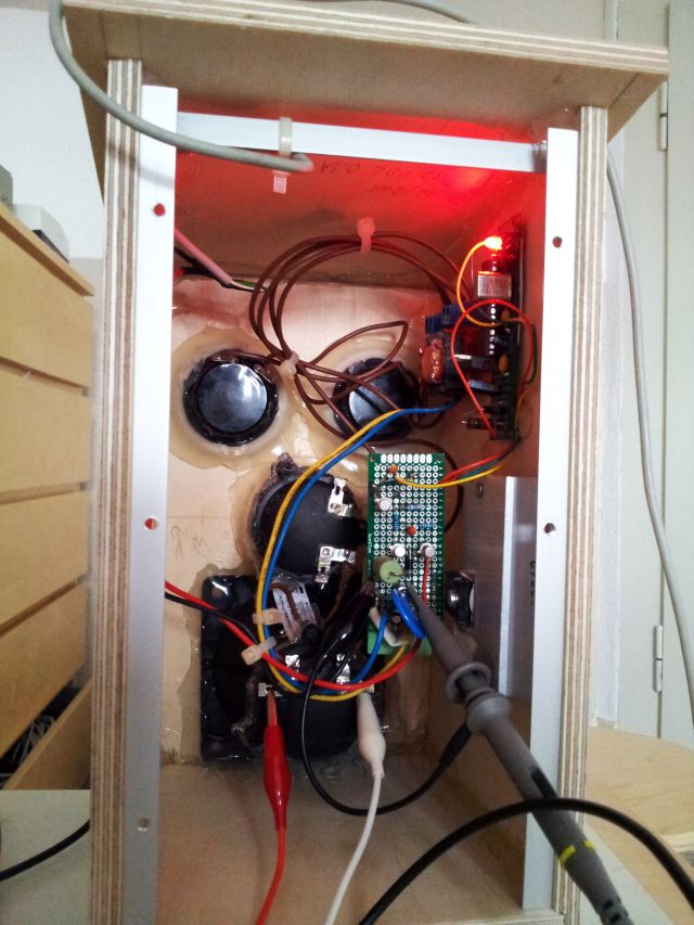
Symptom – easy to describe. Unit turns on, but only briefly, then switches off; over voltage protection light activated at times; a lot of noise on the DC rails when shorting out the safety circuits.

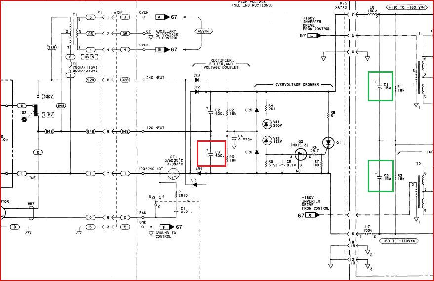
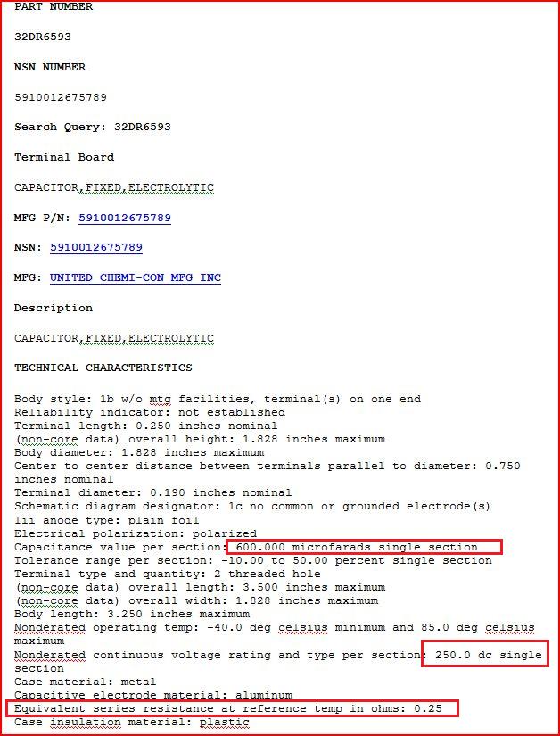
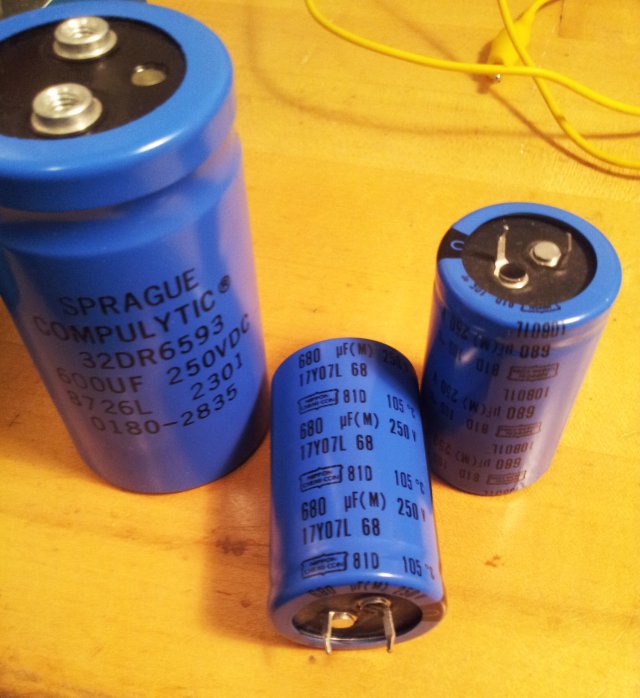
After some probing, the culprit could be located: one of the input capacitors. While this is a common failure mode of other equipment, these caps don’t fail too often for such HP equipment, because only best-in-class components were used, and these are typically run cool, for long life. Still, one of these 32DR6593 SPRAGUE Compulytic caps failed (resistance about 100 kOhm, virtually no capacitance, rapid self-discharge when charged to 50 V for test, framed red in the schematic below).

8663a pwr supply schematic

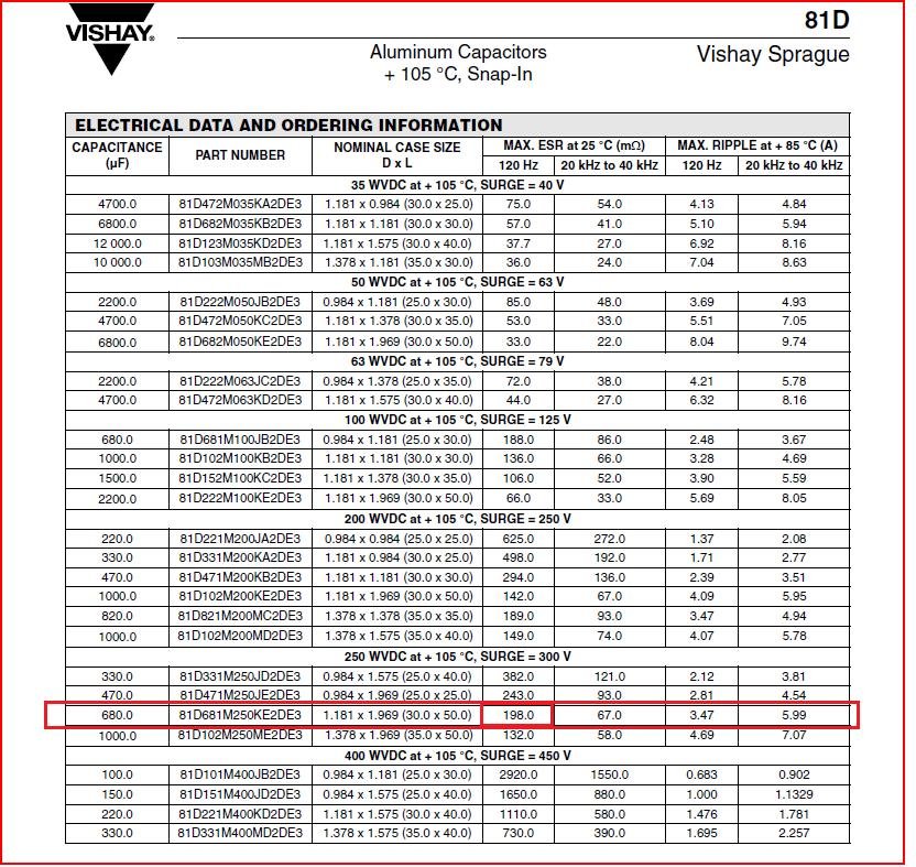
These were replaced by 81D series Nippon Chemi-Con (Vishay) caps. To call this a successful repair, you might wish to check the ESR specifications – the SPRAGUE had about 0.25 Ohms, the Nippon 81D (680 µF, 250 V) has about 0.198 Ohm, good enough. Note that the 600 µF screw-type terminal caps might still be available, but they are pretty expensive, so I opted to for Nippon Chemi-Con, USD 2.50 per piece, surplus, rather than USD 50 for a pair of screw-type caps. I still think it is a good compromise, because this is not about restoring old equipment, but to make this unit working again, quickly, and at lowest cost.

8663a 32dr6593 data

8663a cap vishay 81d

8663a new and old caps

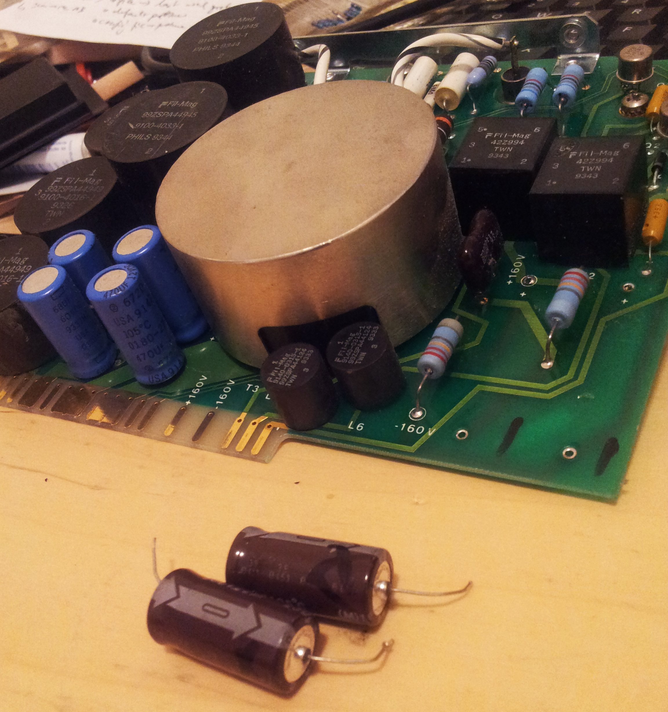
Some repair is also needed on the A7A3 board – there are 22 µF caps that provide a low impedance DC input to the switching transistor, these are essential for operation (framed green in the schematic). They still work, but were hot, and stressed, possibly overstressed, by the dead main cap. Their can be replaced by any good cap, I use Shiangchen GSA T axial caps, 105 deg C rated. Note that the schematic calls for 15 µF, but 22 µF (measuring about 28 µF) were present in the circuit.

8663a a7a3 pwr supply board

With the power supply disassembled, always a good idea to take out the boards for cleaning, and for re-tightening of the screws holding the various TO-3 regulators in place. Some of these were pretty loose (no wonder, with 30+ years of thermal stress on the boards).

After the repair, add thermal compound to the heatsink/cover – this power supply has a rather critical thermal design. Then, make sure to check the insulation resistance and electrical soundness/earth leakage, which is always a good idea after repair of switchmode power supplies.

HP8568B Repair Story: 249, 275 unlock

Quick story from a contributor, no pictures:

8568B Spectrum Analyzer. When switched on – following error codes were displays:
249 unlock
275 unlock

Findings (in German; in short, there was an issue with thw 275 MHz oscillator, C10 had been replaced before, along with Q5; replacing C10 with a high-quality adjustable cap and increasing capacity a bit, this increasing feedback, the issue could be resolved; root cause: oscillator did not start oscillation reliably when powdered up, because of a lossy C10 cap).
##########################################
Der Übeltäter war auf der Platine A18
275 MHz Phase lock Oscillator..
Nach diversen Abgleichen fehlte plötzlich
das Ausgangssignal. Als ich das Modul
herausnahm, sah ich,
dass jemand vorher schon herumgelötet hat.
Das C10 war durch einen billigen Keramik-C
ersetzt, ausserdem war ein neuer Transistor
Q5 eingesetzt.
Am Werktisch liess sich zeigen, dass der
Oszillator nicht immer anschwang. Mit
Betriebsspannung ab und wieder anschalten
scwang der Oszillator dann wieder an.
Ich habe das C10 durch einen hochwertigen
Trimmer ersetzt, die Kapazität etwas höher
eingestellt (mehr Rückkopplung)
und der Fehler war beseitigt..

Es ist auch bemerkenswert, wie relativ stabil
der Osz. freischwingend läuft, trotz der
doch einfachen Schaltung.
##########################################
Thank You Bodo for sharing this.

A13 30 MHz Reference Oscillator: a reasonably quiet oscillator, and a noise cable

A nice little oscillator assembly came my way, supposed to generate about 17 dBm at 30 MHz. Nothing special at first glance, but after checking out its internals, it appeared to be worth a more careful look.

a13 ref osc

A hand-made box, and even more labor intensive assembly work inside. All build by point-to-point wiring, using only the best components available, glass trimmer caps, filters, mica caps – most of these parts are still available today – about 100 USD bom, at least.

a13 upper side

a13 lower side

After a bit of reverse engineering, here the schematic, a modified Colpitts oscillator. Note: base resistor of 2N5109 is 150 Ohms.

a13 schematic

To measure phase noise, connected it to my HP 3585A spectrum analyzer (this is really a great piece of equipment, a bit heavy, but still best of class noise performance and holding this title for the last 35 years….). Connected the oscillator via a 6 dB attenuator, to provide a clean load to the output, rather than dealing with the imperfections of cables, adapters, and the analyzer input.

30 mhz ref osc floor0

Quite shocking, all this noise. The green trace shows the analyzer noise floor. Check, and re-check, still a lot of noise. Too much to be true. After 3 hours of tests, found the issue: a defective BNC cable. Center connector was fine, but both shields were non-connected.

a13 bnc plug

A bit more examination of these cable shows their lousy construction. Not bad for 2 dollars a piece, but you get what you pay for…. the shield is not even reaching to the plug – there is a 5 mm gap from the screen end, to the actual plug. So even if all would have been connected fine, the would still be a lot of leaking, from inside out, and outside in.

a13 rg-58u cable

Notice the BNC plugs – these have a somewhat uncommon construction, the dielectric is covered at the front… not quite according to BNC standard.

a13 bnc cable assy

Clearly visible, the cold solder joint…. Turns out, both ends were open-circuit at the shield.

a13 bnc cold solde

Finally, using a good quality BNC cable (also, using LMR-195 double-screened cable). Looking much better. Noise is down -115 dBc at 10 kHz from carrier. It’s good, but not great. I think one could do better, especially, considering all the pricy parts, and high-quality construction. A good target for a Colpitts osciallator would be better than -130 dBc, at 10 kHz separation.

30 mhz ref osc recheck1

Note the pink trace – this is the bad cable, terminated with a 50 Ohm resistor (with the shield broken at both sides, it is actually a 1 meter wire antenna, with an open-circuit 50 ohm resistor at the end).

Dell Optiplex FX160 – 2 GB – Spinpoint M9T 2 TB: Ubuntu server economizer

Most of my data, manuals, pictures, web sites, databases etc are hosted on a Dell PowerEdge SC1425 (Dual 2.6 GHz Xeon, 2x 3 TB RAID1), which is a great and affordable machine, but has some shortcomings – massive noise, and considerable power consumption; see earlier post PowerEdge SC1425.

Also, it is just one machine, and in case of some severe failure, all data could be lost in case of some unforseeable event like a big thunderstorm hitting the power line… not a frequent issue, but bad enough, if you have to go back to 6-12 months old partial backups.

Therefore, I decided to try a different approach – still use the PowerEdge as the main system, but run a more energy efficient and silent machine for the actual business. After review of various options, a Dell Optiplex FX160 appeared to be a good option. This runs on an Intel Atom 230 @1.6 Ghz CPU, and included 2 GB RAM. The price is right, USD 40 for the unit, including a 2 GB SATA flash drive, and completely fan-less, and noise-less.

fx160 board

For the storage, 2 GB ain’t enough. First, considering some flash drives, but these still come at a hefty price, for 2 TB storage…. A Samsung/Seagate M9T series will be good enough. These are small, silent, efficient 9.5 mm form factor drives.

fx160 spinpoint m9t

A quick test of the read/write speeds:

fx160 read write speed

Read/Write speeds are quite OK, >100 MB/s, plenty to saturate my internet connection, and mirroring the main Poweredge server won’t be an issue anyway – this is all done with the system life, and only by incremental update – not so many files will change from update to update.

Network performance during mirroring from the PowerEdge Server (aka arctur).

fx160  server nload

Quite a lot of power – in such a nice case; “acrux” refers to a star, and is the host name for this unit.
All is run on Ubuntu Server 14.04.3 LTS, including SAMBA (to work as a NAS for various Microsoft Windows based systems, SSH, Apache/2.4.7, and eventually, a printer server).

fx160 acrux

440 MHz ISM Band Amplifier: a few extra milliwatts….

There are quite a few devices that use the ISM (industrial-scientific-medical) band at around 440 MHz to transmit information, like, remote thermometers, or to control some installations, like, garage doors, or for personal communications, like, LPD radios, or cordless headphones. Another general term for these devices is SRD – short range devices, and the short range is ensured by a typical maximum power of 10 mW, chiefly, 10 dBm.

In some cases, it may be desirable to boost the output a bit, especially, if you are out in the woods, or for some experimentation of various kind. Be aware, depending on your country of residence, there may be limits to the allowable power of SRD units, make sure you know the rules!

Various MMIC gain blocks exist to provide amplification and output power, but why not go for a discrete transistor solution, using a BFG541 (or BFG591) device. These 9 GHz/7 GHz transistors are SOT223 devices, very robust and easy to work with, and they are pretty low cost, less than 0.5 USD a piece. All the other parts needed are just sub-1-cent capacitors and inductors, except, maybe, for the electrolytic cap.
The small inductors and capacitors at the input/output improve the input/output match (to 50 Ohm impedance), and provide some low-pass filtering (about 800 MHz).

The test circuit on a piece of perf board (adhesive copper tape used for the back plane). Note that this test circuit still has variable capacitors that were replaced by fixed caps in the final design. Also the bias voltage trimmer can be replaced by fixed resistors, it was just added here for convenience of bias current adjustement during test.

440 mhz amp test circuit

440 mhz amp bfg541

The gain measurements were done at +7 dBm input power. To get accurate results and to avoid overload of the VNA input, a 6 dB attenuator was attached to the output (with 2 Watts load capability), followed by a test cable, and with a 20 dB attenuator, directly at the VNA input. This gave about 26 dB (plus minor cable losses) of attenuation, or about -5 to 0 dBm at the VNA input, which is good. The gain offset introduced by the attenuators was removed by recording a reference trace and subtraction from the measured gain trace.

440 mhz gain

As you can see, well above 15 dB gain, and all reasonably flat (note that this is not the true gain, but the limiting characteristics; gain, at lower input power, is larger). We don’t want too much gain above 800 MHz, otherwise, amplification of harmonics and spurious signals comming from the SRD output (which typically is not filtered very well) could interfere with other communications.

Here a few plots of the output power, at various input levels.

440 mhz amp output pwr

440 mhz amp output pwr vs input pwr

To get about 200 mW output power, about 5 mW (7 dBm) are enough, at 440 MHz, even less, at lower frequencies (in case you need to amplify other signals). 200 mW should be plenty for all practical applications related to SRD or ISM personal devices.

HP 8569B Front Panel Assy Repair: rotary switches

Another 8569B repair, dealing with the aging plastic of the front panel assy rotary switches. Having the variable ref level encoder fixed earlier (ref level encoder repair), the level rotary switches were fixed, by using some small (metric) M1.2×0.25 brass screws.

Most important – the holes to be tapped for the screws need to be drilled quite accurately, using a 0.8 mm drill. This is best done on a milling machine or precise drill press, or with a very steady hand. If you don’t have a drill press, make sure all is as straight and perpendicular as possible.

A M1.2×0.25 tap is then used to thread the parts, make sure to start the tap perpendicular to the surface (a single tap, or machine tap will be fine – no need to use tap sets).

M1.2 screws will fit pretty snug through the contacts, so you might need to use a small screwdriver or similar tool to slightly enlarge the holes of the contacts.

8569b rotary switch repair

Final stage of assembly, still with some of the wires unsoldered…

8569b control assy

8569b control assy front

Vintage IC Stock: listing

For all folks that are into repair of vintage gear, here is another list (earlier list: Vintage Transistors) of circuits that I have in stock.

saj110

There are many more in stock, but these below have been listed and are stored in a way that I can find them easily… Primarily, these are for my private shop&repairs, but if you are in desperate need for one of these goodies, just shoot me a line (I may ask for a fee to cover my expenses&time).
Note that I don’t keep exact stock lists – some of the parts may become unavailable over time. Listings of more outdated ICs – will be added soon.

Location Part Count

K-T01 LA7212 – 1 Pcs
K-T01 M58653P – 1 Pcs
K-T01 LM3915N – 2 Pcs
K-T01 TD62103P – 1 Pcs
K-T01 NE5534AN – 1 Pcs
K-T01 LC24085P – 1 Pcs
K-T01 LC74084P – 1 Pcs
K-T01 UAA170 – 1 Pcs
K-T01 TBA120 – 1 Pcs
K-T01 TBA120S – 1 Pcs
K-T01 SAB2022P – 1 Pcs
K-T01 SAB1046P – 1 Pcs
K-T01 SAJ110 – 1 Pcs
K-T01 TDA2721 – 1 Pcs
K-T01 WD1100V-12 – 1 Pcs
K-T01 TDA2710/1 – 1 Pcs
K-T01 TDA2730 – 1 Pcs
K-T01 TDA3780 – 1 Pcs
K-T01 TDA2560/3 – 1 Pcs
K-T01 TDA1054M – 1 Pcs
K-T01 SAB1009B – 1 Pcs
K-T01 TAA611 – 3 Pcs
K-T01 CA3081 – 4 Pcs

K-T02 Z85C3008PSC – 1 Pcs
K-T02 SN76477N – 1 Pcs
K-T02 4N33 – 3 Pcs
K-T02 TDA2151 – 1 Pcs
K-T02 TDA2160 – 1 Pcs
K-T02 KM6264AL-10 – 1 Pcs
K-T02 MM74C906N – 1 Pcs
K-T02 SN7493AN – 1 Pcs
K-T02 ICM7049AIPA – 2 Pcs
K-T02 SN16913G – 1 Pcs
K-T02 MAX690A – 1 Pcs
K-T02 TL7705ACP – 1 Pcs
K-T02 TDA2320A – 1 Pcs
K-T02 SAJ110 – 1 Pcs
K-T02 TDA1950 – 1 Pcs
K-T02 HM4334P-4 – 1 Pcs
K-T02 TDB0556A – 3 Pcs
K-T02 SN76660N – 3 Pcs
K-T02 TC5508P-1 – 12 Pcs
K-T02 UA733CN – 2 Pcs
K-T02 TAA710 – 3 Pcs
K-T02 TDA3562A – 1 Pcs
K-T02 CA3083 – 1 Pcs
K-T02 ULN2111A – 1 Pcs
K-T02 SAA1027 – 1 Pcs
K-T02 TDA2790 – 1 Pcs
K-T02 TDA2740 – 1 Pcs
K-T02 TDA1170S – 1 Pcs
K-T02 TDA3770 – 1 Pcs
K-T02 TDA4942 – 1 Pcs
K-T02 TBA440C – 1 Pcs
K-T02 TDA1940 – 2 Pcs
K-T02 TDA2591 – 1 Pcs
K-T02 TDA2730 – 1 Pcs
K-T02 TAA630S – 1 Pcs
K-T02 TDA1180P – 1 Pcs
K-T02 TA7630P – 1 Pcs
K-T02 MC14584BCP – 1 Pcs
K-T02 709CJ – 1 Pcs
K-T02 MC1307P – 1 Pcs
K-T02 WIC7015 – 1 Pcs
K-T02 V4001D – 1 Pcs
K-T02 MC14503B – 1 Pcs
K-T02 TDA2140 – 1 Pcs
K-T02 M3-7603-5 – 1 Pcs
K-T02 N82S25 – 1 Pcs
K-T02 N8T10B – 1 Pcs
K-T02 L6506 – 1 Pcs
K-T02 TCA830S – 2 Pcs
K-T02 TAA930 – 1 Pcs
K-T02 TDA2522 – 1 Pcs
K-T02 TDA2532 – 1 Pcs
K-T02 SN76001ANQ – 1 Pcs
K-T02 TDA7250 – 2 Pcs
K-T02 WD1100V-03 – 1 Pcs
K-T02 R5620 – 1 Pcs
K-T02 WIC6020 – 2 Pcs
K-T02 LM339N – 1 Pcs
K-T02 DS8836N – 2 Pcs
K-T02 A10N – 1 Pcs
K-T02 TA7171P – 1 Pcs
K-T02 9602PC – 1 Pcs

IBM Thinkcentre M50 P4 3 GHz: electrolytic capacitor repair

One of my computers, a trusty IBM Thinkcentre Desktop, decided to fail on me. Symptoms – sometime it starts up normal, sometimes it doesn’t. Already hangs at the boot screen. Smells like a hardware issue, and in fact, it is a hardware issue – with some electrolytic caps (note the brown substance leaking out from the top vents; fortunately enough, no damage to the board).

ibm board1

ibm board2

ibm board3

Electrolytic cap failure are a very common feature of modern consumer electronics, the remarkable thing here: only some of the caps failed – 1500 µF, 10 V, and 1000 µF, 10 V. Maybe these see particular load, or they are from a batch that wasn’t all that good. All were high quality Nichicon brand, 105°C, HM series, specially designed for PC motherboards, low impendace, etc.

nichicon hm series electrolytic caps

Board with new caps installed…

ibm board rep caps

All caps were replaced by 1000 µF, 25 V – these were the only caps I had available with the given footprint and capacity range; 100 n X7R multi-layer caps were added (solder side), hopefully, to prolong the lifespan of the electrolytic caps.

ibm board aux caps x7r

These are the culprits… a last look before they go into the bin. Board is working good as new. Let’s see how long the repair will last.

ibm dead caps

EMI Sniffer/Checker

Many designs have been published in the past for various EMI probes. All have there merrits for particular applications. Here, a very handy small probe, especially suited to check enclosures of switch mode power supplies and similar circuits for EMI leaks. The probe has particular advantages for localizing the actual leakage spots, because it only captures fields in its close proximity, unlike many other EMI test probes.

The setup is very low-cost, using the venerable LM386 amplifier to directly drive a small speaker. Gain is set to 200, 46 dB. Sure, you can also hook this up to an oscilloscope, or to the line-in of a soundcard for waveform/spectrum analysis.

emi leak detector schematic

A 9 V battery is used to power the thing.

emi detector

The sense coil – a small ferrite rod, with a coil of about 150 turns, small-diameter copper wire.
emi sense coil2

To protect the coil, seal it with some heat shrink tubing.

emi sense coil1

Happy EMI sensing!

Ultrasonic Pest Chaser: final design

Following up on an earlier post, , design is now complete and a test unit has been completed.

First, a nesting box was made using 9 mm birch plywood. This can be varnished, to any color you like, and is in itself very much weather resistant. All edges and gaps were sealed with hot glue. For added stability, the bottom plate is inserted into a grove of the side and front panels.

rat chaser box1

rat chaser box2

rat chaser box3

rat chaser nesting box drawing

The driver was upgraded a bit, from the earlier version, by using a IRFP460 MOSFET. This is a very sturdy part, and will most likely not fail even under some severe operation conditions. It it can also be mounted to the heatsink in an insulated fashion, without any special washers, etc. – this is the main reason for selecting it.

rat chaser piezo driver schematic

The speakers are 2x KEMO L010,

rat chaser l010 speaker1

rat chaser l010 speaker2

and 2x PTI-1010; one of the PTI-1010 has its horn cut-off; both were fit with two layers of wrap foil to protect the membrane (PTI-1010 has a paper membrane, whereas the L010 has a plastic membrane).

rat chaser pti-1010 speaker

rat chaser pti-1010 speaker cut off

rat chaser pti-1010 speaker response

One key component of the setup, an inductor, in parallel with the speakers. This converts the capacitive load of the piezos to a much more well-behaved load, resonance frequency of the setup is a few kHz. The coil needs to be capable to handle currents of 1 Amp easily, otherwise, it will heat up and may even fail. The one used here may be a bit oversized but it was on hand and still has acceptable size and dimensions.

rat chaser coil

Three of the 4 speakers are mounted in Schedule 40 1.5″ PVC pipe (this pipe is common in the US and dimensions match well the dimensions of the speakers; you can use other types of plastic pipe as well).

rat chaser speaker piupes

The holes in the wood panels are precision machined, for a snug fit with the pipes. Hot glue is used to seal it all together and to firmly lock everything in place.

rat chaser speakers mounted

rat chaser speakers mounted2

Typical waveform during a test run, driving at somewhat above 12 VDC to test system durability… gate drive (yellow) and source-drain voltage (blue).

rat chaser waveform

Final testing…

rat chaser final tests

rat chaser final rear view

rat chaser final front view

Operated from a 12 Volts DC supply, the final tests show that the output voltage is pretty much in line with the allowable voltages for a series connection of two L010 speakers, and flat over the frequency band of interest.

rat chaser rms results

SimonsDialogs – A wild collection of random thoughts, observations and learnings. Presented by Simon.